Autometer 3373 2-Channel Pyrometer - Intake Air Temperature
Installation in a modified Dodge Stealth TT
by Jeff Lucius
Introduction
The Dodge Stealth R/T Twin Turbo and Mitsubishi 3000GT VR4 V6 engine (model 6G72) has two turbochargers and two intercoolers. I have MHI TD04-15G-6cm2 turbochargers (built by TEC) and Cartech/Alamo intercoolers with 2"-diameter steel intercooler (IC) pipes (customized by GT ALLEY). I installed the Autometer 3373 2-Channel Pyrometer mostly out of curiousity. I want to know the temperature of the compressed air leaving a turbo and after going through an intercooler. I am monitoring the left-bank (rear) turbo and intercooler (left front).
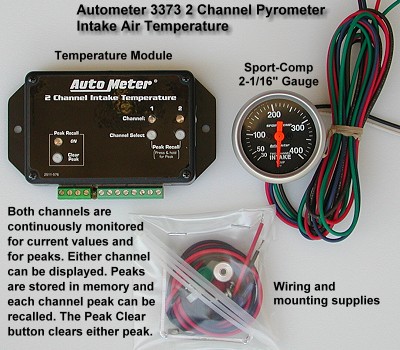 The Autometer 3373 kit consists of two temperature probes, a 2-1/16" (52 mm) gauge, a temperature module, and some wiring and mounting supplies. I paid $257.34 for the 3373 kit from egauges.com. The probes are available separately as part number 5250 for about $50 each.
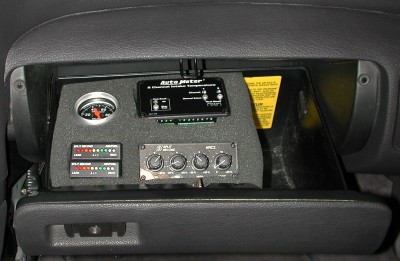
The Temperature Module is a monitoring and peak-recall unit as well as a power distributor. The module connects to ground and a switched +12 volt source to provide ground and power to the gauge and the two probes. Only the gauge's two light wires do not connect to the module. Pressing and releasing a "Channel Select" button on the module displays the current air temperature for that channel. To display the most recent temperature peak on the gauge, press and hold a channel select button until the "Peak Recall" light turns on. At that point, pressing "Clear Peak" button erases that peak value. Otherwise, pressing the "Channel Select" button returns the unit to normal monitoring operation. All peak values are erased when power is removed from the module. Whenever the Temperature Module is supplied power after being shut off it defaults to monitoring channel 1.
The buttons on the Temperature Module are metal and vibrate against the case during normal driving. I found this noise very annoying. Hard rubber or plastic buttons may have prevented this. After installation, I eliminated the vibration noise by placing small strips of black electrical tape across each button. This still allows use of the buttons and prevents vibration.
Autometer describes the temperature probe as a "fast response" thermocouple. However, Autometer does not provide the type of thermocouple (I think it is a K type), the temperature range (I presume it at least includes the 30º to 400ºF range of the gauge), the resolution or accuracy (I am not sure I would need better than 1ºF resolution or accuracy in this application), nor the time constant (also called the response time). The time constant of a thermocouple is the time required to reach ~63.2% of an instantaneous temperature change. Five time constants are required for a thermocouple to stabilize very close to the instantaneous temperature. The bare wire thermocouple of the Autometer temperature probe has a diameter of approximately 0.025 inch. This type of probe typically has a time constant of about 1 second.

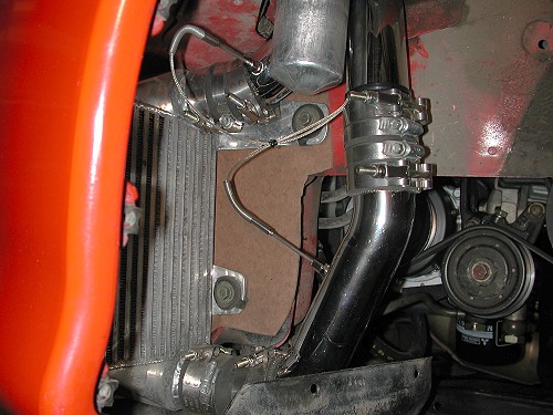
I placed the temperature probes in the two metal pipes (perhaps more properly called tubes because of their thin-wall construction) that attach to the intercooler in the lower right corner of the schematic of the air intake path shown below. The Channel 1 pyrometer is in the pipe from the rear turbo just inches "before" the intercooler. The Channel 2 pyrometer is just inches "after" the intercooler in the pipe that goes to the Y-pipe, which attaches to the throttle body mounted on the intake plenum. I placed the pyrometers here because there should be very little relative temperature change between the turbo and intercooler and between the intercooler and the plenum. In the future I would like to add temperature probes "before" the rear turbo (upper location #2 in the schematic) and in the intake plenum. I could use switches or a patch board to monitor various combinations of the probes.
These instructions supplement Autometer's instructions for installing the gauge and temperature probes and provide specific information for the Dodge Stealth and Mitsubishi 3000GT. The suggested tools include: screwdrivers, socket set, pliers, a 1/8"-27 NPT tap with handle, drill press with an R bit (0.339") or a 21/64" bit (0.328"), liquid thread sealant (such as Permatex High Temperature Thread Sealant, item #59214), 11-mm and 3/8" wrenches, 18-ga insulated multi-stranded wire, electrical tape, and a wire stripper and crimper tool. Please read all of these instructions before beginning this procedure.
Installation of Probes
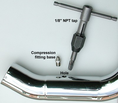
You first need to determine locations for the probes. I decided to tap the aftermarket metal IC pipes at the entrance and exit to the left aftermarket intercooler. These tips are for installation in a metal object, as opposed to plastic or rubber object. Remove the object to be tapped to receive the compression fitting base. I inserted the IC pipe into a vise attached to my table top drill press. Because I do not have an R bit (0.339"), the recommended drill size for a 1/8"-27 NPT, I used the closest, smaller bit I had, a 21/64" (0.328") bit. This size hole worked just fine.
Carefully tap the hole using a 1/8"-27 NPT tap. If you are unfamiliar with this procedure, practice on another tube or metal part first. Notice how the tap is tapered and how the threads on the compression fitting base are tapered. While slowly rotating the tap, work it into the hole, making threads. The farther the tap goes into the hole the larger the diameter of the threaded hole will be and the deeper into the hole the compression fitting base will rest. Test fit the compression fitting base to be sure it will tighten to the correct insertion depth into the pipe or other object. I thought about 1/3 of the fitting should insert into the IC tube. When you are satisfied that the tapping is complete, clean the tube or object so that there are no metal shavings or dust inside.
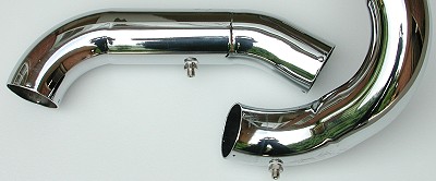
The thickness of my IC tubes allowed only two complete threads. I was not sure this would be enough to secure the fitting in the tube. A pressure test of the intake pipes and several months of operation has so far proved that two threads are enough. Note on the fitting about where the fitting threads into the tube. Apply some liquid thread sealant to the fitting on these few threads. Thread the fitting into the tube by hand and tighten with an 11-mm wrench. Do not over tighten to the point that threads may strip. Allow the sealant to dry.
Before you install the part(s) back on the engine or car, insert the probes so that they extend about half way into the passage and mark the probes. Now install the part(s) on the car. You may want to route the wiring harness for the probe before you install the probe in the part. Slide the compression fitting nut onto the probe. Slide the ferrule onto the probe. The o-ring is not used (its purpose was to keep the fitting, ferrule, and nut on the probe during shipping). Insert the probe into the fitting to the desired depth. Using the 11-mm and 3/8" wrenches tighten the nut onto the fitting. This will compress the ferrule making a tight seal and holding the probe in place. You should complete the entire installation and testing of the Autometer 3373 kit before re-assembling the car, that is, be sure the installation is correct before putting body panels and wheels, for example, back on.
Installation of Temperature Module
1. Determine source for ground, switched +12V power, and switched dash light +12V power. If you have not already located sources for switched power, dash lights, and ground, take a look at my web page 2-wiring-tips.htm.
2. Placement and connections. Decide where you want to mount the Temperature Module. The Module should be within easy reach of the driver. I placed the Module in the glove box. My web page 2-glovebox.htm shows how to drop and remove the glove box. Also shown on that web page is where I drilled a hole in the back of the glovebox for wires to pass through. From the glovebox, wires are routed through lower parts of the instrument panel.
Measure the distance from the probes to the Module. If this distance is greater than 6 feet you need to extend both wires from each probe by attaching additional 18 or 22 AWG insulated stranded copper wire. I needed to extend the wires maybe 4 feet or so to reach the glovebox from the left intercooler. From where I mounted the probes near the left intercooler, the wires on the probes only reached to the firewall opening near the steering column. See my web page 2-dashpanelaccess.htm for more information regarding accessable openings in the firewall. I attached small labels to each wire that extended the thermocouple wires so later I could make the correction connections to the Module.
Installation of Gauge on the A-Pillar
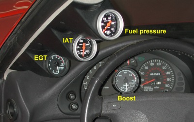
1. Placement and connections. Select a place to mount the gauge. I put it in a gauge pod on the A-Pillar. My web page 2-a-pillar-cover.htm has instructions for removing and installing the A-Pillar cover. To install a gauge pod on the cover, before removing the cover place the pod on the cover and mark lightly in pencil its location. Then remove the cover. Place the pod on the cover where marked and drill holes to attach the pod to the cover with plastic pins or screws. You will also need to drill holes large enough for the gauge wires to pass through the cover. These holes should be away from the pod opening, near where the base of the gauge would be after installed in the pod. Erase the pencil marks and attach the pod to the cover. The picture below shows a single and double pod attached to the cover to make a "triple" pod. You may have to do some minor trimming of the pods to get the best fit to the cover. You may also have to slightly trim the pod opening to fit a 52-mm gauge in it. Be sure the gauge is not too long for the pod. I have seen 60-mm gauges installed in these same pods after trimming the opening a little.
Some gauges have their wires attached to them using a connector. Others, like this Autometer gauge, have the wires "permanently" attached. If this is the case, you will need to cut each wire and attach male and female connectors to each end (such as bullet or quick disconnects, 2-crimpterms.htm). This way you can run the wires and install the A-Pillar cover and then later install the gauge. Be sure to color code or label the wires if necessary.
Be sure the wires from the 3373 gauge are long enough to reach to where you installed the Temperature Module and long enough to extend a few inches out of the A-Pillar pod after the A-Pillar cover is in place. Extend them if necessary. With the A-Pillar cover removed, route the wires down through the dash through the opening near the base of the A-Pillar. I use a straightened wire coat hangar with the wires taped to it. Route the Module wires under the dash to the Temperature Module and attach them to the specified terminals (see the Autometer Installation Instructions). Route the gauge light wires to your light power source (2-wiring-tips.htm).
If you have not already attached the thermocouple, power, and ground wires at the Module, do so. At this point you can test everything. Plug the wires together at the gauge and turn the ignition switch to "ON" (IG1). You will see the needle in the gauge move and an indicator light will be lit on the Module. Turn the parking lights on to see if the gauge lights. If everything works, disconnect the gauge, and install the A-Pillar cover with the gauge wires extending through the pod a few inches. Attach the gauge and slide the gauge into the gauge pod.
Finishing Up
After you are satisfied that everything is installed correctly, install all the stuff you removed to get to the probe, Temperature Module, and maybe gauge mounting locations. Start the engine and see if everything works OK. You may want to pressure test the intake track (2-pressuretester.htm) to be sure there are no leaks at the probe connections.
Page last updated June 19, 2004.