Wiring Tips - Power, Lights, and Ground Connections
for the Mitsubishi 3000GT/Dodge Stealth
by Jeff Lucius
Introduction
These instructions will help you connect the power and ground wires inside the cabin for aftermarket gauges, meters, control units, or any electronic device that does not tap into the engine control module (ECM) connector. There are two choices for power connections: ignition-switched +12 V (IG1) and constant battery +12 V (BATT +). For devices that tap into any of the ECM wires, use the power and ground wires at the ECM connector (see, for example, 2-safcii-instal.htm or 2-arm1instal.htm). The +12 V light wire by necessity for all devices must tap into another source. I use the dash lights rheostat switch connector for this. The ground wire attaches to a fastener on the "firewall" near the clutch pedal.
The tools and supplies needed include: a Phillips screwdriver, a trim tool (or similar thin-edged device), some 22-16 AWG insulated female and male bullet connectors (or insulated quick disconnect connectors), a wire cutter/stripper/crimper tool, some snap-splice connectors or other type of similar connector, some insulated 18 AWG multi-strand wire, a few cable ties, black, yellow, red, and white electrical tape, a wire cutter, and a volt-ohm meter. You may want to solder some wire connections, instead of using snap-splice connectors, then wrap them or maybe use shrink tube. If so, you will need supplies and tools for that. Please read all of these instructions before attempting this procedure.
Power wires
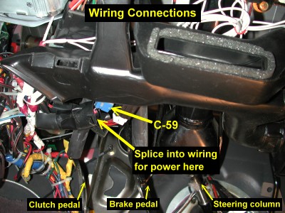
For both constant and switched +12 V power I use the wiring to the Ignition Switch harness connector C-59. Specifically, I tap the white wire that goes to C-59 from the fusible link for constant power and the black with white stripe IG1 wire for switched power. When the ignition switch is in the "ON" position (where it comes to rest after starting the engine), the ACC (accessory), IG1 (switched 1), and IG2 (switched 2) paths are all powered. If it is important that your device be available from the ACC key position then tap into the blue ACC wire. If it is important that your device be available when the ignition key is in the START position, then IG1 must be used. IG2 is available only from the "ON" key position. I have used IG1 for switched power for all my aftermarket devices.
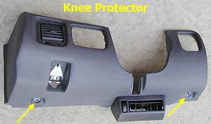
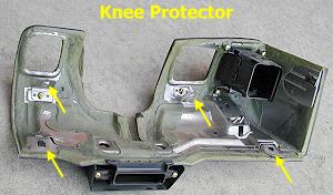
You gain "easy" access to C-59 and its harness by removing the Knee Protector Assembly.
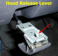
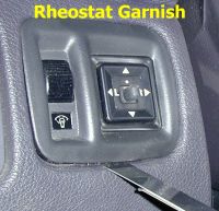
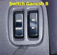
 Remove the two brass Phillips screws in the hood lock release handle. Slide the handle and its bracket to you (toward the back of the car) to slide the mounting tab out of its slot. Take the release cable off the handle. Pry under the edge of the rheostat garnish using a thin, wide, strong-yet-flexible tool. You can use a professional trim removal tool or make one yourself. Slotted screwdrivers are typically too thick to easily slide under the edge of the garnish. Pull the rheostat assembly out a little and disconnect the rheostat connector first. Then disconnect the remote mirror switch connector. Pry under the edge of switch garnish B and then pull the assembly out a little. Disconnect the electrical connectors by pressing on the lever and pulling the two pieces apart. Remove the two brass 10-mm bolts that are at the lower two corners of the knee protector. Remove the two black 10-mm bolts that are accessed from the opening where the two switch assemblies were. Pull the knee protector panel off.
After the knee protector panel is removed locate the blue C-59 connector as shown in the photograph below. Indicated by the lower yellow arrow, there is a bundle of wires to the left of the connector that is wrapped with some plastic insulation and tape. Unravel this plastic wrap to gain access to the wires you need. Save the plastic wrap and re-use it when you are finished.
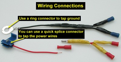
At this point you need to tap some wires. My technique and "philosophy" below present one method to connect multiple devices by tapping the power wires only once. I tap the power wire using a quick splice or "snap splice" connector. See 2-crimpterms.htm for pictures of different types of insulated crimp terminals. If you prefer, you can remove a small bit of insulation from the power wire and then twist on or solder on the new wire. I have used quick splice connectors at the ECU connector, here at C-59, and at the rheostat and have never had any problems in the 5 years I have been adding aftermarket devices to my 1992 Stealth TT. Wrap the splice/tap with electrical tape. Regardless of the tapping method, at the end of the new wire is a single insulated, female, bullet receptacle connector (or a quick disconnect if you prefer) that is crimped on and then wrapped with electrical tape. I use red tape for the constant power (BATT+), yellow tape for the switched power (IG1), black tape for ground (GND), white tape for lights (RHEO), and green or blue tape for other device-related connections. Do this part right, by whatever method, and you should never have to mess with this again. Be sure the wire is long enough to reach a conveniently accessible place after the knee protector is re-installed. You can add a name tag to the wire to avoid confusion in the future.
To add a device to these power wires I make up "Y"s as shown below, consisting of one insulated, male, bullet, crimp connector and two female bullet connectors. I crimp on the connectors, pull on them to be sure they are secure, wrap them with electrical tape, and then test for continuity using an ohmmeter. The reading on the ohmmeter should be the same as when you cross-connect the two ohmmeter probes together (usually some value less than 1 ohm). The new device connects to one of the female connectors and the other female connector is ready for the next "Y". In this manner I create a wiring jungle under the dash but only have to tap the power wires once. You can make multi-fingered wire "adapters" instead of two-fingered "Y"s. I placed an inline 10A fuse on the BATT+ and IG1 power wire taps as a safety precaution (not shown). I use cable ties to bundle wires together and to fasten them to parts under the dash to keep them out of the way (especially out of the way of my shoes).
Dash Lights Connection
For devices that need a switched power source for lighting, I tap into the dash light rheostat switch. The rheostat is a good place to connect the +12V dash light wire that many gauges and control units have. The harness side of the connector (connector D-40 in the circuit diagrams for 1992 models) is shown below. Wire/pin 4 (green with white stripe) is the +12V into the rheostat. Wire/pin 3 (black with yellow stripe) is the ground into the rheostat. Wire/pin 2 (black) is ground out of the rheostat. The rheostat dims the lights by increasing the resistance to current ground. Tapping into the +12 volt in wire (green with white stripe) will supply light-switched, full illumination to your unit. Tapping into both +12 V in wire and the ground in wire (black with yellow stripe) will give dimming capability to the your unit's light. However, some units use the ground wire for other purposes than just a light. In this case the unit's ground wire should be connected to the chassis (if +12 V comes from the harness) or the ECM (if +12 V comes from the ECM).
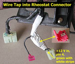
The picture above was taken when I had the instrument panel (the dash) out of the car. The rheostat connector (D-40) is most easily accessible with the knee panel removed. However, you could probably also make the connection by removing just the garnish and leaving the knee protector in place. Be sure you route a long wire, with the appropriate connector on the "far" end, under the dash before making the splice.
Ground Wire Connection
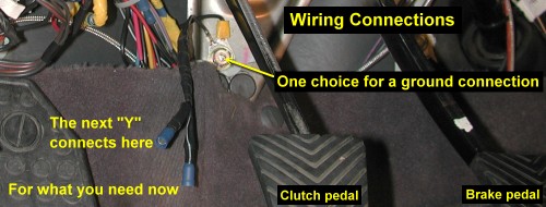
For the chassis ground connection (GND), battery negative terminal, I use a bolt located under the clutch pedal. See the picture below. I connect my first tap wire to a ring connector and place the bolt through the ring connector. The knee protector does not need to be removed for this, or the carpet. I use "Y" connectors as described above to add ground connections for new devices. An inline fuse is not needed.
Knee Protector Installation
After you are finished making your new power connections, re-install the knee protector if you removed it. Be sure the tab on the left side of the protector goes into the slot in the dash and that the hood release cable is routed correctly. Install the four bolts. Add the switch assemblies and the hood release handle. The tab on the top of the hood release handle bracket must insert into the slot in the knee protector.
Page last updated January 7, 2005.