Instrument Panel Removal
on the Mitsubishi 3000GT/Dodge Stealth
by Jeff Lucius
Introduction
These instructions are for removing the instrument panel (also called the dash) on my 1992 Dodge Stealth Twin Turbo. For other models, you may have to improvise a little, particularly if you have a mechanical speedometer cable (non-turbo models) or a passenger-side air bag (1994 and newer models). Here is my convention for the use of directions. Front is toward the front of the car. Back is toward the back of the car. Left side or left hand is on the driver's side. Right side or right hand is on the passenger's side.
Read all of the instructions and look at the pictures before you begin. The tools required are 1/8" and 1/4" slotted screwdrivers, #2 Phillips screwdrivers (short and long handles), pliers, string (about 24-inches long), 10-mm and 12-mm sockets, a 3-inch and two 6-inch socket extensions, a socket wrench, forceps or long, needle-nose pliers, and a trim-removal tool (which can be homemade). I either replace screws and bolts in their holes after a part is removed or I use labelled plastic storage containers or bags to keep all the little parts sorted and not lost. I also use masking tape to mark some of the wires. This is to remind me to reconnect them as much as to identify what they go to.
You will be disconnecting a lot of electrical connectors. Nearly every connector is relesed by pressing a small lever located somewhere on either the equipment side or harness side of the connector. Each connector is a little different. Take the time to inspect each connector to see how to release it. Rarely does it take a lot of force to pull the connector apart if the release lever is depressed sufficiently. You should not need a tool to disconnect an electrical connector. The exception might be to press on the release lever for a hard-to-reach connector.
Pre-Removal
Before you start, be sure you have security codes, if necessary, for the radio or other devices. If you have power seats, be sure that they are moved as far rearward as possible. If you have power windows, put them in the up or down position as you prefer. Disconnect the battery negative cable first, then disconnect the positive battery cable. You must remove the floor console before you remove the instrument panel. I have instructions for this at 2-floorconsole.htm.
Removal
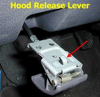
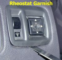
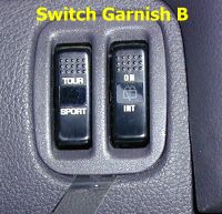
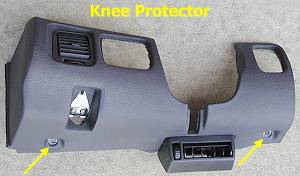
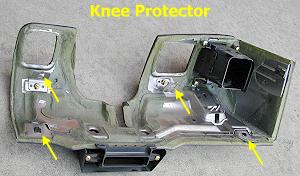
 1. Knee protector. Remove the two brass Phillips screws in the hood lock release handle. Slide the handle and its bracket to you (toward the back of the car) to slide the mounting tab out of its slot. Take the release cable off the handle. Pry under the edge of the rheostat garnish using a thin, wide, strong-yet-flexible tool. You can use a professional trim removal tool or make one yourself. Slotted screwdrivers are typically too thick to easily slide under the edge of the garnish. Pull the rheostat assembly out a little and disconnect the rheostat connector first. Then disconnect the remote mirror switch connector. Pry under the edge of switch garnish B and then pull the assembly out a little. Disconnect the electrical connectors. Remove the two brass 10-mm bolts that are at the lower two corners of the knee protector. Remove the two black 10-mm bolts that are accessed from the opening where the two switch assemblies were. Pull the knee protector panel off.
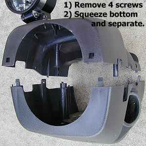
2. Steering column cover. Remove the four #2 Phillips screws from the bottom half of the steering column cover. The front two are longer (toward the dash) and the back two (toward the steering wheel) are shorter. The two halves of the cover snap together. Carefully squeeze the bottom piece to un-snap the two pieces. Slide the top half out around the steering wheel. If you are having trouble doing this, then wait until step 10 (when the steering column is unbolted) to remove the top half.
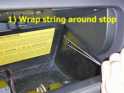
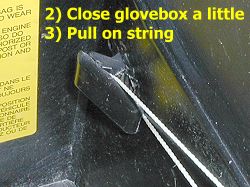
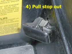
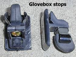
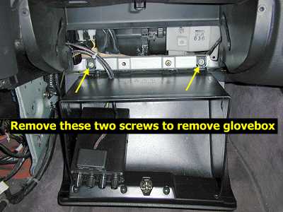
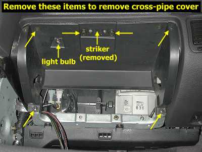
3. Glovebox. Remove the glovebox stops with a string as shown in the pictures below. Be sure you close the glovebox a little when pulling on the string to release the stop. Let the glove box open all the way (you can support it with your feet) and remove the two screws on the cross bar. Set the glovebox aside. Remove the striker (note that it bends outward). Now remove the two, 1-3/8", 10-mm bolts near the striker, the two screws in the upper two corners of the cross pipe cover, and the two, 1-1/4", 10-mm bolts in the lower two corners. Pull out the cover a little and remove the light bulb connector by rotating it. Set the cover aside.
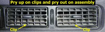
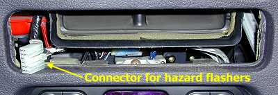
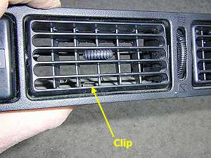
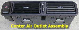
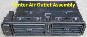
4. Center air outlet assembly. Use a small slotted screwdriver, or similar tool, to pry up on the two clips shown below in the center air outlet assembly. At the same time, pry out on the edge of the assembly with the trim tool. Slide the assembly out a little and disconnect the hazard flashers electrical connector.
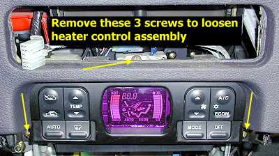
5. Heater control assembly. You do not need to remove the heater control assembly, but you do need to disconnect it from the instrument panel. Remove the three screws shown in the picture below and let the asembly rest on the full-auto air conditioner control unit (the "flat" black box below it). If this unit is not there then disconnect the electrical connectors and remove the heater control assembly.
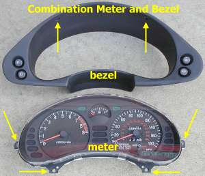
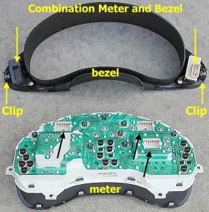
6. Combination meter and bezel. Remove the two screws from the upper portion of the combination meter bezel. Use the trim tool to pry out on each lower corner of the bezel to release the clips (see picture below). Pull the bezel straight out a little and disconnect the electrical connectors on each side. Slide the bezel out from behind the steering wheel. Remove the four brass screws from the combination meter. I used forceps to extract the screws once they were loose. Pull straight out on the combination meter to release the electrical connectors. Slide the meter out from behind the steering wheel.
7. Speakers. Remove the two small speakers (or the plugs) from the top of the dash. Carefully pry up on them with the trim tool or a screwdriver. They just snap in. Disconnect the electrical connectors.
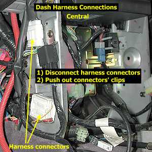
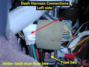
8. Three of the nine harness connectors. There are nine wiring harness connectors that must be disconnected to remove the dash. The three shown here are easiest to disconnect before you drop the steering column (step 10). Disconnect the two connectors on the floor console/instrument panel mounting bracket. Use pliers to compress the wings on the grommets that hold the harness-side of the connector. Press or pull the grommets through the bracket when the wings are compressed. Disconnect the connector shown below that is near the fuse box (in the driver's foot well).
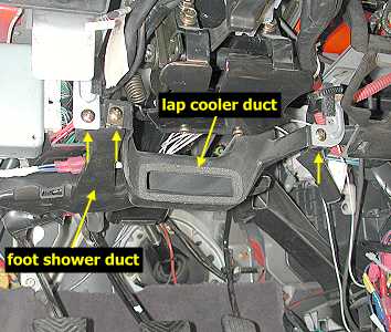
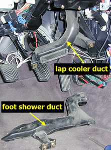
9. Ventilator ducts. Before you lower the steering column, two ventilator ducts must be moved out of the way. Disconnect the foot shower duct and lap cooler duct from each other and from their mounting brackets, as shown in the pictures below. Remove the foot shower duct. The lap cooler duct can just hang there or be removed. These plastic pieces just snap or slide together.
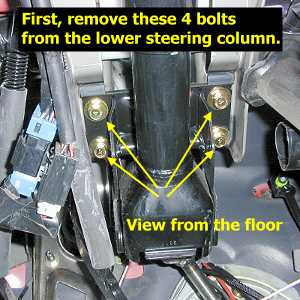
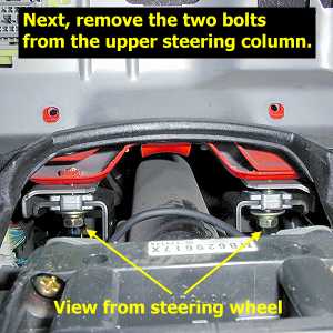
10. Steering column. Remove the four 12-mm bolts from the lower mounting bracket of the steering column. Sit in the driver's seat and support the steering wheel while you remove the two 12-mm bolts from the upper bracket. Gently lower the steering wheel and column to the floor while checking to see that wires and the brake and clutch pedal return springs are not in the way. If you need to, support the wheel on a block.
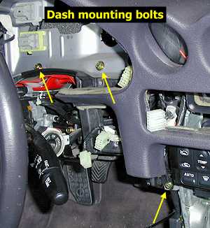
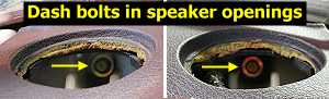
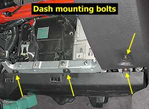
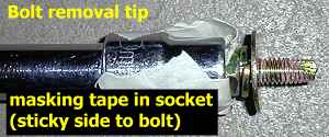
11. Panel bolts. There are six bolts and three screws that must be removed now. Remove the two 10-mm bolts that were behind the combination meter and the single 10-mm bolt that is in the floor console mounting bracket. Remove the three screws that attach the under cover to the cross bar that the glovebox was attached to. Remove the two 10-mm bolt to the lower right of the glovebox opening. Remove the 10-mm bolts at the top of the dash that are accessed through the dash speaker openings. Some masking tape (sticky side to the bolt then twisted and wrapped around the socket) can be used to prevent the bolts in the speaker openings from falling once removed.
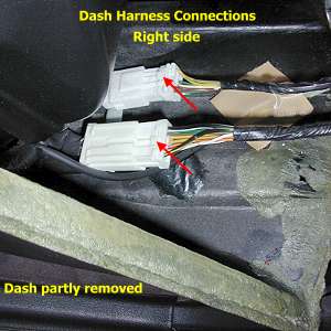
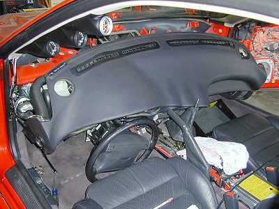
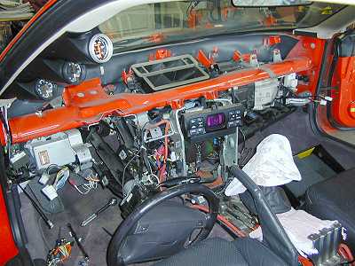
12. Instrument panel. The only items left to disconnect are six more electrical connectors. Place a rag on the shifter stick (which I did after the picture below was taken). Pull the dash toward you a little. If it is stuck, double check that you have removed all the bolts and screws. Pull the dash out enough so that it can rest against the shifter stick. Disconnect the four connectors on the left side and the two connectors on the right side. Lift the dash up and remove it from the car. Again, be sure that all electrical connectors are disconnected and that no other wires or objects are snagged on the instrument panel. The dash weighs about 18 pounds.
While Its Out of the Car
If you need to make repairs or modifications to the instrument panel, now is the time to do it. The defroster garnishes can be replaced (2-defrgarnish.htm). Cracks or tears in the vinyl cover can be repaired. The combination gauges (the three gauges in the center of the dash) can be repaired or replaced (2-combogauges.htm).
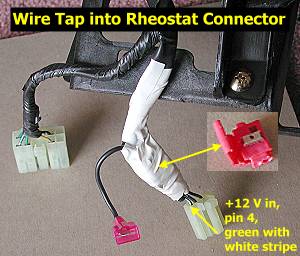
Another procedure to consider is adding a tap into the dash light rheostat switch. The rheostat is a good place to connect the +12V dash light wire that many gauges and control units have. The harness side of the connector (connector D-40 in the circuit diagrams for 1992 models) is shown below. Wire/pin 4 (green with white stripe) is the +12V into the rheostat. Wire/pin 3 (black with yellow stripe) is the ground into the rheostat. Wire/pin 2 (black) is ground out of the rheostat. The rheostat dims the lights by increasing the resistance to current ground. Tapping into the +12 volt in wire will supply light-switched, full illumination to your unit. Tapping into both +12 V and ground in will give dimming capability to the your unit's light. However, some units use the ground wire for other purposes than just a light. In this case the unit's ground wire should be connected to the chassis (if +12 V comes from the harness) or the ECU (if +12 V comes from the ECU).
After you have made any repairs or modifications is an excellent time to clean and treat all the vinyl and rubber surfaces with a protectant. I use Mequiar's Natural Shine Vinyl and Rubber Protectant. Mequiar's product includes a cleaner and a UV protectant. It does not leave an artificial or greasy appearance. The degree of shine is determined by the amount applied and by repeat applications. You may want to let the vinyl and rubber surfaces dry a little or wipe off excess protectant before re-assembling the instrument panel.
Installation
Before you install the instrument panel, check all the bolts and screws on the panel to be sure they are tight. Start all mounting bolts by hand or with just the socket and extension (no ratchet) to avoid stripping the threads.
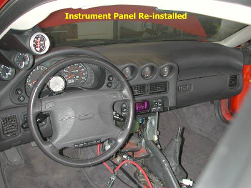
1. Instrument panel. Place a rag on the shifter stick. Slide the dash into the car and into the approximately correct position. Re-connect the electrical connectors, four on the left side and two on the right side. Slide the dash up and forward. There is a mounting post in the middle near the windshield. Be sure all the mounting holes line up.
2. Panel bolts. Install the two bolts through the speaker openings. Install the bolt in the floor console mounting bracket. Install the two bolts behind the combination meter. Install the bolt to the lower right of the glovebox.
3. Glovebox. Insert the plastic cross pipe cover part way and install the light socket (twist to secure). Push the cover all the way on. Add the bolts to the lower two corners but do not completely tighten them. Partially insert the two screws near the upper corners. Add the bolts near the striker and now tighten all bolts and screws. Add the striker (it bends out). Bolt the glovebox to the cross bar. Insert the stops with the door part closed by squeezing the spring clamps on the stop. Open the glovebox all the way to set the stops.
4. Steering column. Insert the upper two bolts first (do not torque down) and then the lower four bolts. Finger tighten the bolts until all have been installed; the column will have to move around a little to line up all holes. After all bolts are in then torque them down to 8 ft-lbs (12 Nm).
5. Ventilator ducts. Re-install the ventilator ducts.
6. Three of nine harness connectors. Re-connect the one connector near the fuse box and the two connectors on the floor console mounting bracket. Be sure to insert the grommets into the correct holes.
7. Speakers. Install the speakers or plugs after re-connecting their wires.
8. Combination meter and bezel. Install the combination meter by sliding it in behind the steering wheel with the top tilted in. Push the meter in firmly until the connectors snap together. I used forceps to insert the four screws. Slide the bezel in from the right and re-connect the electrical connectors on each side. Push the bezel into place so that the clips catch on each side. Add the two screws. I had the front wheels off the car when I did this, so I was able to move steering wheel back and forth for an easier install.
9. Heater control assembly. Re-attach the heater control assembly with its three screws.
10. Center air outlet assembly. Push in the center air outlet assembly part way and re-connect the hazard flashers connector. Push in the assembly until the clips snap in.
11. Steering column cover. Slide the top of the cover on first then the bottom. Snap the pieces together and add the four screws.
12. Knee protector. Install the knee protector. Be sure the tab on the left side of the protector goes into the slot in the dash and that the hood release cable is routed correctly. Install the four bolts. Add the switch assemblies and the hood release handle. The tab on the top of the hood release handle bracket must insert into the slot in the knee protector.
Post-installation
Install the floor console assembly. When you are done, reconnect the battery positive cable first, then the negative cable last (always!).
Page last updated March 17, 2002.