AC Compressor Replacement
in the DOHC Mitsubishi 3000GT/Dodge Stealth

by Jeff Lucius

Introduction

These instructions supplement the instructions in the service manual for removing and replacing the air conditioning compressor in a the DOHC Mitsubishi 3000GT and Dodge Stealth. For tips on troubleshooting the air conditioning system in our cars, please take a look at my web page 2-ac-tips.htm.

The tools and supplies required are a hydraulic jack, jack stands, two wheel chucks (blocks of wood are fine), lug wrench or the appropriate socket and ratchet for your wheels, a torque wrench that goes up to 100 ft-lbs, a small flat-head tool for some Stealth owners to remove the wheel center cap, 10-mm, 12-mm, 14-mm, and 12-mm-deep sockets and ratchet (a swivel head ratchet may be required), 3" and 6" socket extensions, 2' to 3' breaker bar, six feet of cord, pliers, wrenches in the same sizes noted for the sockets, a small hammer, and safety glasses (for working under the car). I keep the various loose parts and fasteners organized in separate plastic bags or containers. Please read through all the instructions before starting this procedure. The work below was performed on a 1992 Dodge Stealth R/T Twin Turbo with custom intercooler piping and the oil cooler moved to in front of the condenser. While the AC compressor is out of the car, consider replacing the front oxygen sensor; you will never have easier access to it with the engine in the car.

Because of Federal laws, the potential for refrigerant to deplete the ozone layer 10 to 30 miles above the earth's surface, and the danger of exposing skin to very cold evaporating refrigerant, special precautions must always be used when handling the refrigerant in the air conditioning system. Deliberate venting of CFC-12 (also known as R-12, freon-12, or the trade name Freon) to the atmosphere has been prohibited since 1992 and release of HFC-134a (also called R-134a) has been prohibited since 1995. HFC-134a has been in use in USA cars since the 1994 model year. Unless you are certified to perform this type of work and have the necessary equipment, do not attempt any repair procedure that might allow freon to be released. If there is refrigerant in the system, have a certified shop remove the freon for you before you start this work. You should get a credit from them toward recharging your system. Do not release the refrigerant into the atmosphere!

AC system diagram

Pre-Removal

If there is refrigerant in the system, have a certified shop remove the freon for you before you start this work. You should get a credit from them toward recharging your system. Do not release the refrigerant into the atmosphere!

You should replace the o-ring on the end of any AC pipe you disconnect. There is a good chance a used o-ring will not crush properly during re-installation and so cause a leak in the system. Lightly coat the o-ring with the proper refrigerant oil before installation. FREOL S-83 or SUNISO 5GS is used with R-12 refrigerant. SUN PAG 56 oil is used with R-134a refrigerant. The o-rings are odd sizes and fairly small so you may have to take them off to match them up at your supplier. Mitsubishi does sell the o-rings individually. Here are the o-rings and sizes you need for a 1992 model manufactured starting January 1, 1992. Note: the part numbers for other model years and even for different production dates for the same model year may be different.

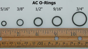
1992 (starting 9201.01) 3000GT/Stealth AC O-Rings
Part No. Size Location
MB946449 5/16" Sensing line from expansion valve to suction line
MB946604 3/8" Line at condenser to receiver drier
Line at receiver drier from condenser
Line at receiver drier to expansion valve
Line at expansion valve from receiver drier
Intermediate connection of line between
    receiver drier and expansion valve
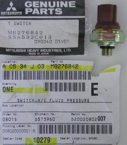
none 1/2" Pressure switch on receiver drier
MB946605 9/16" Discharge line at compressor
Discharge line at condenser from compressor
Intermediate connection of discharge line
    between compressor and condenser
Line at expansion valve to evaporator
MB946607 3/4" Suction line at compressor
Suction line at the evaporator

AC O-rings

If you are going to replace the compressor, then have another one on hand. The compressor in 1991 to 1993 models, which use R-12 refrigerant, is Mitsubishi-manufactured model FX105VS. The 1994 and newer models, which use R-134a refrigerant, use Mitsubishi compressor model MSC105. Both compressors are scroll-type compressors. If you are going to have your compressor rebuilt, figure it will take from 5 to 10 business days, which includes shipping time. Always install a new or remanufactured clutch assembly (the part with the pulley on it that engages and disengages the compressor with the drive belt) with the new or remanufactured compressor.

It is also accepted service procedure to replace the receiver drier (always!) and expansion valve (usually) when the compressor is replaced, and to flush the condenser, evaporator and lines (not the expansion valve or compressor because they are not free flowing, and you will be replacing the receiver drier). The expansion valve assembly for my 1992 model (production date of 9203.1) is MB630405 and it includes the 5/16" o-ring MB946449. The receiver drier (called "Receiver Assy, A/C" in CAPS) for my car is part number MB813589. The pressure switch on the 1991-1993 (R-12) receiver drier is part number MB276842, and it includes a new 1/2" o-ring (in CAPS: Switch, A/C Refrigerant Pressure). Aftermarket receiver driers usually do not come with a pressure switch (but there will be a plug installed with an o-ring to keep the receiver drier sealed).

Be sure to check in CAPS or with your supplier to get the correct part for your year and model car. The part numbers varied for the various models. In CAPS see illustration 55-430.

You should be aware that Mitsubishi no longer sells or stocks new "R-12" compressors (model FX105VS) used in 1991-1993 3000GT/Stealth models. Buying a remanufactured compressor is very much recommended over buying a used compressor. You really have no idea what the condition of the seals are in a used compressor, especially if it has been sitting unused for any period of time. Prices for a remanufactured "R-12" compressor with clutch range from about $300 to about $600, depending on the source. You can also have your compressor rebuilt. List price for the compressor, when it was still available, was about $710. The list price for the compressor clutch assembly, which is still available, is about $337 and for the receiver drier assembly is about $98. The dealers listed on my Garage Page offer up to 25% club discount on parts for Team3S or 3SI members.

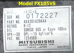
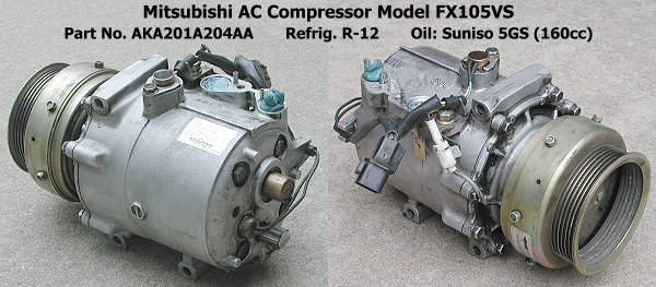
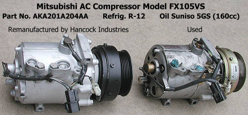
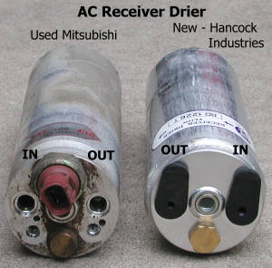
If you are looking for remanufactured AC components, including the compressor assembly, then consider contacting Hancock Industries (now Hodyon Intelligent Solutions) located in Abilene, Texas (1-800-289-8282). I purchased a reman'ed FX105VS compressor with clutch from them for $289.59 plus core charge and a receiver drier for $29.49 (Spring 2002). In May 2007, I bought an aftermarket receiver drier (also called an accumulator or filter/drier) for my car from Hodyon for $14.29 (their part number is 04-4931A). Discount dealers such Norco Mitsubishi wanted about $78 for it (probably a very fair price compared to what many of your local dealers want). Hoydon did not carry the expansion valve. These prices are excellent compared to the quotes I received from many local sources. I contacted Hancock Industries using the 800 number above. The sale representatives are very knowledgeable about the parts I needed plus courteous and professional. In 2002, the remanufactured compressor and receiver drier were at my house in less than 48 hours. Shipping charges were less than $11. I also purchased an $8 UPS return service label from them to make it easy to send Hancock Industries my old compressor and get my $100 core charge refunded. In 2007, again the receiver drier was at my house in less than 48 hours for a shipping charge of $10.55 (total for the receiver drier was $24.84, about a third of what the discount Mitsubishi dealers want).

Another source for AC components for our cars is http://www.discountcompressor.com/ (reman compressor with clutch for $315, no core charge; accumulator/drier for $45; expansion device $45; June 2007).

Manual diagram for compressor removal

Removal

1. Disconnect negative battery cable. With the ignition off, remove the negative battery cable from the battery. Be sure you have security codes for any devices that might need them before you do this.

2. Lift and support car, remove wheel. You must remove the driver's side front wheel to gain access to the alternator drive belt tensioner. I have some tips for lifting and supporting the car at my web page 2-raisecar.htm and removing the wheel at my web page 2-tirerotation.htm. Generally, you want to loosen the wheel lug nuts a little, lift the car, rest the front cross member near the rear of the control arm on a jack stand, and finish removing the wheel. Be sure the car is securely and safely supported before you proceed.

3. Intercooler pipes. Non-turbo models can skip this step. I have aftermarket intercooler pipes and removed enough of the pipes to make access easy to all parts I needed to get to. If you have the stock IC pipes, remove the pieces above and near the compressor. For my setup, I needed to move the suction hose (the next step) first, drain one quart of radiator coolant (an under cover must be removed), and un-attach the front of the top radiator hose. Block the openings in the remaining IC pipes with rags to prevent objects from entering.

4. AC suction line. Remove the two 10-mm nuts toward the back, the 12-mm nut on the side, and the 12-mm bolt at the front of the air conditioning suction hose. Lift the hose until it no longer moves easily and tie it off to the hood using a cord.

Suspended AC suction hose

5. Front splash shield. Remove the three tapping screws, the two 10-mm bolts, and the five clips with screws from the plastic splash shield in front of the wheel well. The clips with screws are removed by uncsrewing the screw part a little then pulling the whole clip out. If the screw does not want to back out, then try putting a little upward pressure on the grommet by lightly prying around the base with a small screwdriver.

Fasteners

6. Engine room side cover. This cover is behind the driver's side front wheel and conceals the belts and pulleys. Remove the two clips with screws on the bottom and the three 12-mm bolts near the top of the side cover. Set the side cover out of the way.

Engine room side cover

7. Tensioner pulley and drive belt. Before adjusting the tensioner, take a moment to note the tension on the belt between the idler and crankshaft pulleys as shown in the figure at the end of the web page. Loosen, but do not remove, the 14-mm bolt in the center of the tensioner pulley. With a 12-mm socket, rotate the tensioner bolt counterclockwise to lower the pulley and reduce tension on the belt. Stop when the belt is loose enough to remove. If you plan to re-use the drive belt, then mark the outer edge of the back of the belt (flat side) with chalk so that you can re-install it the same orientation. Remove the belt and inspect it; replace if old (every 30,000 miles or 3 to 4 years) or if it shows signs of wear. Note how the ridges in the belt fit in the grooves of the different pulleys.

Drivebelt tensioner

8. AC condenser fan assembly. Mark the two electrical connectors with masking tape next to the condensor fan (the one near the alternator) so you know which goes where (actually, the two connectors are slightly different). Disconnect the two connectors by pressing on the levers and pulling up. Remove the four 10-mm bolts on the fan assembly and pull the assembly out through the top. The upper mounting "brackets" on the radiator for this fan have sharp corners which could benefit from filing at the edges.

9. Alternator wiring harness connections and brackets. Grasp the bottom of the rounded plastic cover that protects the top cable connection (positive "B" terminal) and raise the cover. Remove the upper 10-mm nut and lower 10-mm bolt, and pull the harness away from the alternator a little. Disconnect the harness completely from the alternator by pressing on the connector lever and pulling the connector away from the alternator. Identify the bolt that attaches the oxygen sensor connector to the alternator bracket and remove the bolt and oxygen sensor connector bracket.

Alternator wiring harness

10. Alternator and bracket. Remove the two 14-mm bolts on the driver's side of the bracket (the longer one goes on the bottom). Loosen both 12-mm upper bolts but remove only one. Now support the alternator with one hand as you remove the other bolt. Maneuver the alternator in its bracket up through the top. More information concerning the alternator removal is in my web page 2-alternator.htm.

Alternator bracket

11. Compressor wiring harness. Press on the lever and pull down on the electrical harness connector to separate the two pieces.

Compressor connections

12. Refigerant lines. Loosen the 12-mm bolts that attach the two pipes to the compressor and wait for any residual refrigerant to escape. There should be very little. Do not let any escaping refrigerant get near exposed skin. Remove the suction hose and very carefully clean the dirt off the fitting while avoiding introducing any dirt into the opening. Cover and seal the opening with a plastic bag. Suspend this end with the rest of the hose. Stuff a small piece of clean rag into the suction opening in the compressor. Remove the discharge hose and cover and seal the end with a plastic bag. Stuff a small piece of clean rag into the discharge opening in the compressor. You will eventually want to remove the o-rings from the end of the pipes to match them up with the correct-size replacement. Take care to not damage the fittings on the lines.

Detail of suction hose end

13. Mounting bolts. Loosen the top bolt one or two turns. Loosen and remove the bottom two bolts. Go back and loosen the top bolt some more until the compressor turns. Now cradle the compressor in your left hand while you remove the bolt with your right hand. Set the bolt aside and wiggle the compressor out through the top. All three bolts are the same size. The compressor weighs about 19 pounds (8.6 kg).

Compressor lower bolts

Compressor removed

Compressor with grime   Compressor label

Compressor FX105VS

Compressor FX105VS - old and reman'd

Installation

While the compressor is out, check the ends of the open refrigerant lines to see how clean they are. The seals and o-rings degrade as the air conditioning system ages introducing air into the system, and letting the refrigerant and oil escape. The moisture in the air helps to form acid in the system which can attack hoses, o-rings, and other components. The debris formed by degrading components can collect in the condenser. So it is a good idea to remove the condenser and have it flushed to check for accumulation of debris. If there is a lot of debris, then consider having the rest of the system flushed, except for the compressor, receiver drier, and expansion valve.

It is also a good idea, and accepted industry practice, to replace the receiver drier when replacing the compressor. Try to keep the new receiver drier sealed at all times until the refrigerant lines are connected to it. Moisture in the air can saturate the desiccant in the receiver drier after a few hours of exposure (capacity is about one tablespoon), making the new receiver drier unusable. The receiver drier cannot be flushed so moisture, or debris or contamiants, cannot be removed. The receiver drier is easy to remove but will require some new o-rings for the two lines. An additional o-ring may be required if you must transfer the pressure switch from the old receiver drier to the new one. A new switch from Mitsubishi comes with an o-ring and costs $20.25 from Tallahassee Mitsubishi ($27 list price). Use a vice to hold the body of the receiver drier and a 1-1/16" or 27-mm wrench to remove the switch. The receiver drier should be marked for "in" (from the condenser) and "out" (to the expansion valve) lines. The factory receiver drier has an extra port which could be used for a second switch.

Receiver Drier - old and new    Pressure switch for recevier drier

1. Compressor. Transfer the electrical harness brackets from the old compressor to your new or remanufactured one. Using pliers pull the roll pins where the hoses attach out of the old compressor, and transfer them to the new compressor; just lightly tap them in with a hammer so they are perpendicular to the surface. The reman'd compressor from Hancock Industries came with the RPM sensor and pressure switch installed. It also had about 4 ounces of oil in it. To check to see if oil is in the compressor and to collect a small amount for use on the o-rings, remove the cap on the compressor suction port and slowly tip the compressor until a small amount of oil drains out into a bag or jar or onto some wax paper. Note whether the compressor is dry or the amount of oil present (the manufacturer should have listed the amount of oil they added) for use later when the system will be recharged.

To assure proper distribution of oil in the compressor first set the compressor on its pulley end for one minute. Then reach inside the pulley and rotate the shaft 6 to 12 times. Do not rotate just the pulley because the internal clutch is not engaged and the pulley does not rotate the shaft.

Clean oil and dirt off the three mounting bolts. Lower the compressor into the engine compartment (it will rest on the lower part of the mounting bracket) and install the top bolt by hand at least a few turns. You can use a socket but no ratchet. This minimizes the chances for crossthreading. Similarly, install the lower two bolts, then torque them all to 30-35 ft-lbs. Connect the electrical harness connector.

If you have not done so already, remove the old o-rings and clean the ends of the suction and discharge hoses. Using oil from the compressor or the appropriate oil for your refrigerant, lightly oil new o-rings (a 9/16" MB946605 for the discharge line and a 3/4" MB946607 for the suction line) and install them on the ends of the hoses. Attach the hoses to the compressor being careful to line up the holes in the hose end with the dowel on the comrepessor.

2. Receiver Drier. Disconnect the wiring harness from the pressure switch and the two refrigerant lines. Loosen the bolt on the bracket and slide the receiver drier up and out of the engine bay. If necessary, install a pressure switch in the new receiver drier, minimizing the time the receiver drier is open to the atmosphere. Replace the o-rings on the two refrigerant lines with new lightly oiled o-rings (both are 3/8" MB946604). Slide the new receiver drier into its bracket and attach the two refrigerant lines. Tighten the bracket tension bolt.

3. Alternator and other components. Installation of the rest of the stuff is basically the removal procedures performed in reverse order. Protect the radiator fins with some cardboard. Tape the condensor fan electrical connectors out of the way. The picture below shows the correct orientation to fit the alternator through the space available.

Alternator installation

If you are re-using the drive belt, be sure to install it in the same orientation as it had before removal (same side facing the wheel well). Insert the belt from above. Turn it "sideways" to fit it in between the alternator pulley and the AC pipe. Correctly tension the drive belt using its tensioner pulley. Before installing the plastic covers and wheel, temporarily install the IC pipes and battery negative cable and start the engine to check the belt operation. If the belt squeals it is either misaligned or too loose. I found that my old belt squealed when installed "backwards" from how it was removed. It did not squeal when installed in the same orientation. If you have messed with both drive belts, spray a little water on one belt at a time to see which is squealing. A misalligned belt will stop squealing for a very short time after water is sprayed on it, but the squealing quickly comes back louder than before. If the belt is loose, the squealing will immediately get louder. Also note that there is just a little play in how the alternator bolts in. If misalignment is a problem, loosen all four bracket mounting bolts (this may require again removing an IC pipe), reposition the alternator, and tighten the bolts to see if this helps. Do not tighten the belt too much because this can lead to shaft bearing failure over time.

Here are some links concerning drive belt adjustment.
http://www.gates.com/brochure.cfm?brochure=1026
http://www.ridgeautoparts.com/tips/the_charging_system1_2.htm

http://www.utfleets.com/library/features/accessory_drive_belts.htm

Alternator drive belt adjustment

After you are satisfied the drive belt is installed correctly, disconnect the battery negative cable and re-install the other parts. Tips for mounting the wheel are on my web page 2-tirerotation.htm. The last thing to do is re-connect the negative battery cable.

Recharging refrigerant

After you are all finished, have a certified AC shop check for leaks and recharge the system with refrigerant. Verify the correct amount (160 +/- 20 cc or 9.8 +/- 1.2 cu. in. or 5.41 +/- 0.68 oz.) and type of oil is in the compressor and AC system. The oil the factory puts in the compressor is enough to lubricate the entire system and is carried through the system by the refrigerant. Some of this oil is trapped in various components and should be replenished if just replacing one of the following components or removed if the component was not replaced and the system was not flushed. If you have flushed the condenser (but not the rest of the system), replaced the receiver drier, and used a new or reman'ed compressor with oil in it, then the retained oil in the evaporator may cause the system to contain too much oil. Too much oil will increase the discharge air temperature. But too little oil may cause compressor failure from inadequate lubrication. Be sure there is the correct total amount of oil, 160 +/- 20 cc or 9.8 +/- 1.2 cu. in. or 5.41 +/- 0.68 oz., in the system before sealing it up. One thing to consider is that if nearly all the refigerant leaked out of the system, much of the oil probably went with it and only a residual amount remains in the lines and components.

The AC shop should first vacuum the system for 20 to 30 minutes, drawing out any air and moisture in the system. They will then add refrigerant and oil, and usually a dye for leak testing. My 1992 model holds about 960 grams (2.11 pounds or approximately 34 ounces) of R-12 refrigerant.

Recharge 1

Recharge 2


Back Home Forward

Except for the small gif and jpg images, the content, images, photographs, text, and multimedia displayed are Copyright ©2000-2002 by Jeff Lucius and K2 Software. All rights reserved. No part, section, image, photo, article, or whole of this site may be reposted or redisplayed without permission of the author.
Page last updated June 19, 2007.