| WARNING. Asbestos may be contained in the dust produced by clutch wear. DO NOT blow the dust out with compressed air and DO NOT inhale the dust. DO NOT use gasoline or petroleum-based solvents to clean out the dust. Use brake system cleaner and a rag to clean the dust off of clutch components and the inside of the housing. Properly dispose of the contaminated rags and cleaner. |
| Part | lbs (kg) |
|---|---|
| Transaxle | 125 (57) |
| Transfer case (5-spd) | 24 (11) |
| Flywheel | 21.5 (9.7) |
| Clutch housing | 15 (6.8) |
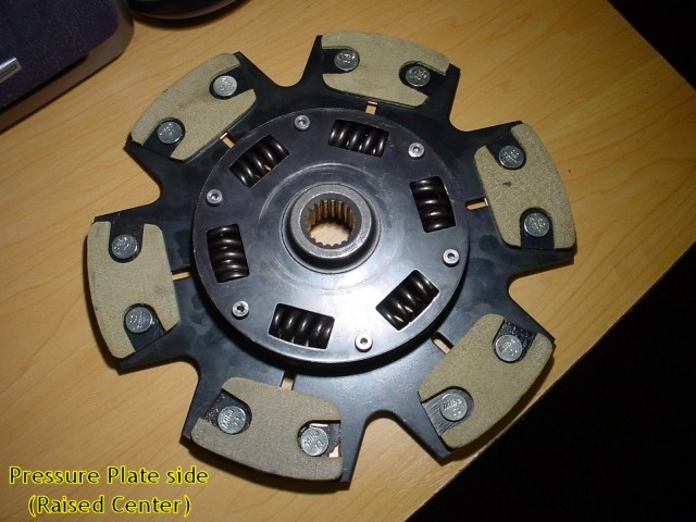
| Clutch disc | 5 (2.3) |
| Back | Home | Forward |