Speedometer Gear Replacement
on the Mitsubishi 3000GT/Dodge Stealth
by Jeff Lucius
Overview
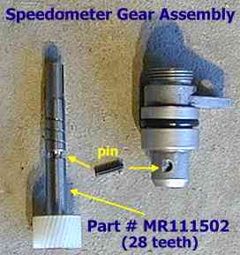
The manual-transmission speedometer gear is a part that should rarely need to be replaced. However, if you have a 5-speed manual transmission manufactured before February 1993, you may want to switch from the 27/36 ratio gear (Mitsu part # MB811064, 27-teeth) to the 28/36 ratio gear used after February 1993 (Mitsu part # MR111502, 28-teeth). This switch will reduce the registered speed by about 4%. This change is still within the acceptable speedometer error of -5% to +10% cited by Mitsubishi in their service manuals.
The tools needed are common ones: a flat-head screwdriver; 10-mm and 12-mm sockets with extensions; pliers; a 10-mm open-end wrench; a small punch; a hammer or mallet. All pictures are located near the end of this article.
Pre-removal
I actually performed this switch with the transmission removed from the car but the speedometer gear is easily accessed with the transaxle still in the car. You may have to make some changes to the instructions below for your particular intake setup. You will need to remove the battery so make sure you have any security codes that may be required for devices such as the radio. Step 1 here is the only essential one.
1. Battery, tray, and washer tank. I have a seperate help page for this at "Battery and Washer Tank Removal". Disconnect the negative battery terminal first (always!). Then disconnect the positive terminal. Both are 10-mm nuts on the stock connectors. Remove the hold-down bar (10-mm nuts again). Lift the battery out of the car. Remove the four 12-mm bolts near the corners of the tray. Disconnect the washer electrical connector and fluid hose near the passenger's-side strut tower. See the pictures below. Lift the battery tray and washer tank out part way and disconnect the washer pump electrical connector (see picture). Remove the tray and washer tank from the car. Keep the washer fluid hose high to avoid spills. Clean your hands and tools if you suspect battery acid got on them.
2. MAS and air filter. Remove the intake air filter and the mass air sensor. This is a simple as just loosening one hose clamp for my ARC2 setup. It is a bit more complicated for the stock setup or K&N equipped cars.
3. Clutch vacuum pipe (AWD cars). Remove the metal pipe that runs across the corner of the battery and then down below the MAS. There are spring-type hose clamps at each end plus a bracket at the front end (12 mm bolt). In addition, a sliding clamp was attached to the battery hold-down bar.
4. Intake hoses. For turbo cars, remove the Y-pipe, the main intake hose that the MAS connects to, and the intake hose to the rear turbo (I leave the vacuum hose attached to the intake hose and disconnect it from the stock boost controller solenoid). I am not sure if the intake hose and resonator will be in the way for non-turbo cars.
For the turbo cars, now is a great time to inspect the compressor wheel on the rear turbo, to check all the vacuum lines, to replace that stock BOV or check the seals on that aftermarket BOV. For all cars, the fuel filter is also easy to get to now, as well as the ISC motor on the throttle body.
Removal
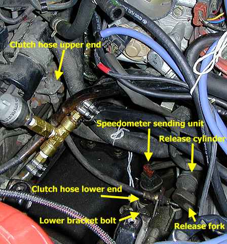
You may find it easier to work around the speedometer gear assembly if you tie hoses and cables out of the way with some string.
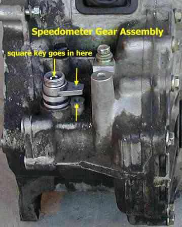
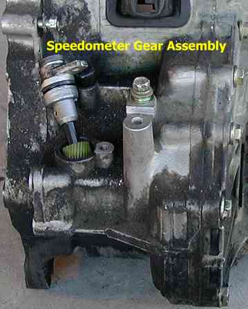
1. Speed sensor. Unscrew the speed sensor (Mitsu part # MB622090, all years) from the top of the gear assembly. You do not need to seperate the electrical connector from the sensor. For the FWD versions it is the speedometer cable that is disconnected. Carefully remove the small square pin that sits inside the top of the gear assembly below the speed sensor or cable you just removed. This pin is what interfaces the rotating gear to the electrical sending unit or the cable. Without this pin, you will get no speed signal for our speedometers. Store it in a safe place (for replacement, it looks to me from the CAPS software that it may be part of the sensor or cable part number).
2. Gear assembly. Remove the bolt that holds the assembly to the transaxle case. You may need to pry on the assembly with a screwdriver of flat bar to loosen it. Raise the assembly straight up and take it to your workbench.
Gear Replacement
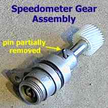
Knock the retaining pin out of the assembly to allow the gear itself to be removed. Clean the outside of assembly with a clean cloth. I don't think using a solvent on the rubber O-ring would be a good idea. Insert the new gear and re-install the rolled pin.
Installation
1. Gear assembly. Clean the surface of the transaxle case where the gear assembly inserts with a clean cloth until all grease has been removed. Insert the gear assembly back into transaxle. I assumed that if I could not rotate the gear shaft inside the assembly then it was properly meshed with the grooves on the front differential case. Bolt the assembly to the transaxle case.
2. Electrical connector. Install the square interface pin. Screw on the speed sensor or cable.
Post-installation
Follow the pre-removal instructions in reverse and be sure to connect the negative battery terminal up last.
Page last updated March 17, 2002.