Fuel Injectors
in the Mitsubishi 3000GT/Dodge Stealth
by Jeff Lucius
Introduction
This short note briefly describes the type of fuel injectors used in the Mitsubishi 3000GT and the Dodge Stealth. For more complete explanations of how fuel injectors work, please see the books, articles, and on-line sources in the References section at the end of this note. What is described here is basically the type of fuel injectors used in our cars, what must be done to use injectors from the turbo models in the non-turbo models, and upgrade suggestions for turbo models.
Fuel injectors are described using the following characteristics:
1. Flow rate
- by volume = cc/min
- by mass = lb/hr
2. Internal coil resistance
- low (2-5 ohm)
- high (13-22 ohm)
3. Driver signal
- voltage controlled (saturated)
- current controlled (peak-hold)
4. Fuel rail attachment
- top feed
- side feed
5. Valve design
- pintle
- disk
- ball
Discussion
1. Flow rate.
This is the nominal amount of fuel released by the injector when it is in a "static" state, that is, the valve is held open for a certain time period and the amount of fuel released is measured. RC Engineering performs these tests on injectors and issues a report like this one for the stock injectors in my Stealth TT, 2-rc_inj_380.htm.
When the volume of fuel is measured, the flow is reported in cc/min (cubic centimeters per minute). When the fuel mass is measured, flow is reported in lb/hr (pounds per hour). To convert between the two types of measurements, either divide cc/min by 10.5 or multiply lb/hr by 10.5. This conversion factor is derived from the average density of gasoline, which is about 6 lbs/gal. However, gasoline density can range from 5.76 to 6.34 lb/gal (690 to 760 g/L, grams per liter).
All turbocharged 3S (3000GT/Stealth) models (all years) use a nominal 360cc/min (~34 lb/hr) fuel injector. All non-turbo 3S models use a nominal 210 cc/min (20 lb/hr) fuel injector.
2. Internal coil resistance
A spring inside the injector keeps the valve closed when there is no current to the injector. When current flows, a solenoid inside the injector pulls the valve open against the force of the spring. How fast the solenoid can open the valve depends on the solenoid coil electrical resistance. Coils with larger-diameter wires and fewer turns have lower resistance and open the valve more quickly than high-resistance coils. Also, less voltage is required to obtain optimal current flow in low-resistance solenoids.
All turbo 3S models use a low-resistance fuel injector (2 to 3 ohms). All non-turbo 3S models use a high-resistance fuel injector (12 to 16 ohms). The Denso 550 cc/min injectors I installed in my 1992 Stealth turbo had a nominal 2.7 ohm resistance.
3. Driver signal
Injectors release fuel when the valve opens. Fuel flow is relatively constant once the valve is open, so the longer the valve is open (the drive time), the more fuel flows. The valve opens when current flows through the solenoid inside the injector. Typically, battery voltage is applied to the injector and the circuit is completed through a ground path inside the engine control module (ECM). Using switching transistors, the ECM closes and opens the connection to ground to open and close the injector, respectively.
In general, there are two types of fuel injection driver circuits: voltage controlled and current controlled. Voltage-controlled circuitry uses the resistance of the overall circuit to limit the voltage in the circuit and therefore the current through the injector coil windings. When low-resistance injectors are used (like in the turbo models) an external resistor is added to the circuit. The non-turbo models do not have the external resistor and instead use high-resistance injectors. Current-controlled circuitry is used with low-resistance injectors only, without the external resistor, and current flow is limited by controlling the gain of the driver transistor.
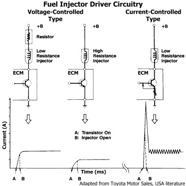
Current-controlled circuitry is often called peak-hold circuitry. The initial current to the injector peaks around 4 amps or more for a very short time to open the valve quickly. Then the current drops to about 1 amp (or the minimum amount needed) to hold the valve open. Peak ... hold. Because only low-resistance injectors are used in peak-hold circuitry, low-resistance injectors are often mistakenly referred to as peak-hold injectors. In fact, low-resistance injectors are used in both voltage-controlled and current-controlled circuits.
Because high-resistance injectors are used only in voltage-controlled circuitry without an external resistor, they are often referred to as saturated-type injectors. The full battery voltage is applied to the injector and the internal resistance of the injector solenoid limits the current. The system voltage saturates the injector.
Mitsubishi uses voltage-controlled circuitry in the 3S cars. All turbo 3S models use low-resistance fuel injectors with an external resistor (left-most example in the figure above). This resistor is often called a ballast resistor. However, Mitsubishi calls it "Resistor, Engine Control" with part number MD145962 (all years). All non-turbo 3S models use high-resistance fuel injectors (middle example in the figure above). The current rise time is longer (distance between A and B in the figure above) for high-resistance injectors than for low-resistance injectors in voltage-controlled circuitry. Also, the current in the injector coil is less for high-resistance injectors than for low-resistance injectors, which allows better longevity in the high-resistance injectors. The ECM increases the duration of the pulse (that is, the amount of time the current is applied) to compensate for the slower solenoid response of the high-resistance injectors.
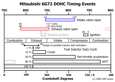
The disadvantages of using the voltage-controlled circuitry in the turbo models are that the resistor introduces heat loss in the circuit and the high peak amps are not supplied to the injector solenoid. The result is an injector that opens faster than the high-resistance injector, because of the faster responding solenoid (less turns, thicker wires), but the response (opening time) is longer (less "crisp") than in current-controlled circuitry. Should the owner of a Mitsubishi 6G72 DOHC engine be concerned over this? Probably not. Look at the figure below. The fuel injector is likely activated very late in the combustion stroke or during the exhaust stroke before the intake valve is opened (more details on my web page 2-fuelinjection.htm). A slight delay in the opening of the injector valve is not critical. Only when RPM are 8000 and above (which is beyond stock factory redline), when there are only 15 ms or less for the injector to activate, does the slightly slower opening time begin to matter.
 The major differences then between the turbo and non-turbo models are the external resistor and the programming of the ECM. The service manuals show that a longer drive time is used for the non-turbo models than for the turbo models. For example, at idle the standard value for the drive time is 1.7 to 2.9 ms (milliseconds) for turbo models but 2.5 to 3.7 ms for non-turbo models.
To understand why the turbo injectors, which flow 360 cc/min, should not be directly swapped into the non-turbo engine, let us look at the amount of current that flows in each type of injector. Remember, E = I x R, that is, volts equal amps times ohms, or amps equal volts divided by ohms. The total resistance in the circuit and the battery voltage determine the current flowing through the injector solenoid. In our cars, the current path goes from the battery, through fuses and the ignition switch, then through the MFI (or engine control) relay to the injector with the ECM completing the path to ground.
First, consider the voltage-controlled circuit in the turbo model. Assume there is a nominal 12 volts in the circuit and that the switches, relays, ECM, and wiring have minimal resistance. The external resistor has a value of about 6 ohms. For a series circuit such as this, we add up the all the resistances to get total the total resistance: 6 ohms (resistor) plus 2.5 ohms (injector) is 8.5 ohms. Divide the 12 volts by 8.5 ohms to get about 1.4 amps in the circuit and the fuel injector coil.
For non-turbo injectors, if 12 volts is applied and the injector coil has a resistance of 13.8 ohms, then a 0.87 amp current flows through the injector. If the turbo injector is placed in the non-turbo engine without adding the external resistor, then the overall circuit resistance would be only about 2.5 ohms, instead of 13.8 ohms, and about 4.8 amps would flow through the injector solenoid. While this setup would function, the extra current will overheat the injector solenoid, eventually causing injector failure.
If installing our turbo injectors in our DOHC non-turbo engines, then the turbo's resistor must be added to keep from overheating the injectors. An airflow signal conditioner, such as the Apex'i S-AFC, must also be added to compensate for both the differences in drive time and extra fuel injected with each "squirt" of the injector. The ECM itself should not care about the switch.
4. Fuel rail attachment
The fuel rail attaches to the top of our injectors. This is called a top feed design. Other injectors use a side (or galley) feed design where the rail encircles the injector. Toyota and Nissan tend to use this side-feed design, while Honda and Mitsubishi tend to use the top-feed design.
5. Valve design
There are three basic valve designs used with variations on each: pintle, disk, and ball.
The pintle-type valve is the earliest design but still popular. And it is the design used on our cars. The solenoid lifts the pintle out of an orifice to release fuel. For our DOHC models, there is an additional orifice with a "figure 8" design, as can be seen on my web page 2-inj360.htm. The pintle is also visible. The problems with the pintle design include increased chance of clogging in the small orifice area, slower response time because of heavier armatures used to lift the pintle, and reduced service life.
The ball-type injector uses a ball (actually half a sphere) to seal the metering orifice, rather than a pintle. This allows the use of a lighter armature and so response time is faster than for pintle types. There is also less wear for a longer service life. The orifice can be designed with multiple openings for a wider spray pattern plus more fuel can be delivered for a given drive time.
The disk-type injector eliminates the armature and the solenoid acts directly on the flat disk through the core of the injector body. The flat disk rests on a seat that has an orifice in it. This arrangement is even lighter than the ball-type for an even faster response time. This disk and seat design also results in less deposit build up at the orifice and longer service life.
If upgrading our injectors, the turbo owners should consider ball or disk type injectors because the faster response time of the injector (over the pintle style) should partially offset the lack of peak-hold circuitry in our setup.
Summary
Non-turbo injectors:
- 210 cc/min (model number depends on the year of production and whether the engine is SOHC or DOHC. The service manuals have the details.)
- high resistance, 12-16 ohms
- voltage-controlled circuitry with long-duration driver signal
- top feed fuel rail
- pintle valve
Turbo injectors:
- 360 cc/min (same model number for all years, Mitsubishi identifier BDL360, made by Nikki as part number INP-014)
- low resistance, 2-3 ohms, with a 5.5-6.5 ohm resistor in-line with the injectors to reduce current
- voltage-controlled circuitry with short-duration driver signal
- top feed fuel rail
- pintle valve
If installing our turbo injectors in our DOHC non-turbo engines, then the turbo's resistor must be added to keep from overheating the injectors. An airflow signal conditioner, such as the Apex'i S-AFC, is required to reduce the air-flow signal to compensate for the differences in drive time and injector flow rate. The ECM itself should not care about the switch.
References
John Baechtel, 1997, Chevy TPI Fuel Injection Swapper's Guide: SA Design, 128 p.
Dan Barnes, 1999, Inside Fuel Injectors: Sport Compact Car, Vol. 11, issue 6 (June 1999), p. 192-207.
Chrysler Corporation, 1988, 1990 Laser Technical Information Manual: Part number 81-699-9002, various pagination.
Chrysler Corporation, 1990, 1991 Stealth Technical Information Manual: Part number 81-699-0114, various pagination. Available on-line at 2-stim.htm.
Jeff Hartman, 1993, Fuel Injection - Installation, Performance Tuning, Modifications: MBI, 160 p.
Charles O. Probst, 2001, Corvette Fuel Injection & Electronic Engine Management: Bentley Publishers, 392 p.
Ben Watson, 1997, Chevrolet Fuel Injection: Motorbooks International, 192 p.
http://www.sdsefi.com/injectors.htm
http://www.rceng.com/technical.htm - Selecting the proper injector
http://www.supras.com/~riemer/sonictech/fuel_injectors/RCtech.html - Injectors by Russ Collins (RC Engineering)
http://yarchive.net/car/injectors.html
http://yarchive.net/car/fuel_injection.html
http://yarchive.net/car/fuel_pressure.html
Any of the Mitsubishi or Chrysler Service Manuals for the 3000GT or Stealth
Page last updated January 18, 2006.