Instructions for Changing the Fuel Injectors
in the Mitsubishi 3000GT/Dodge Stealth 6G72 Engine
by Jeff Lucius
Overview
Installing higher-capacity fuel injectors is a joy reserved for owners of the turbocharged versions of our cars. The installation of larger injectors must be accommanied by some sort of device to modify the mass air signal going to the ECU and by "larger" turbos. The 450 cc/min injectors are well matched with the 13G turbo upgrade. For 15G turbos, 550 cc/min injectors are adequate but 620 cc/min injectors are a better choice. The "twice-as-big-as-stock" 720 cc/min injectors are a good choice for the huge GT-Pro GT368-SX turbos. The Apex'i Super AFC can handle up to 540 cc/min injectors (50% larger than stock). For 550 cc/min injectors, the HKS VPC will work with specific chips for your car's setup. The best all around choice is the GT-Pro/Split Second ARC2 kit, which can handle any injector from stock (360 cc/min) to 720 cc/min and any performance mod, including turbo upgrades. For the normally-aspirated engines, the injectors may be removed for cleaning or replacement and these instructions are easily modified for those engines.
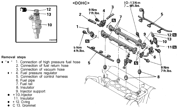
Getting to the injectors is basically the same operation as getting to the spark plugs. In fact as long as you are in there, you might as well check the plugs (see my spark plug instructions). It should take you several hours to upgrade your injectors. The tools you will need are: slotted and #2 Phillips screwdrivers; 3/8"-drive socket wrench with 3", 6", and flexible extensions, and 10-mm, 12-mm, and 13-mm sockets; pliers, forceps; thin-blade pocket knife; 3/8"-drive torque wrench. You will need, of course, 6 fuel injectors (the Denso 550s, part number 195500-1370 are a direct replacement). The new injectors should come with new o-rings and grommets for their tops; if not, the part numbers are MD614813 (o-ring, fuel injector) and MD614805 (sheet, fuel injector). You can try re-using the grommet-like insulators on the bottom of the fuel injector, but for $2 each I replaced them, part number MD087060 (insulator, fuel injector). The gasket between plenum and intake manifold is a rubbery-type substance and fairly durable, but this will be a good time to replace it if it is worn or damaged.
You do not need to disconnect the fuel rails from each other or the fuel lines. All hoses and the throttle body can stay connected to the plenum. Only the Y-pipe must be disconnected from the throttle body. If you are a novice, then read these instructions a couple of times, look at the pictures carefully, and set aside 3 or 4 hours. It may be helpful to re-install bolts or nuts as soon as a part is removed or place them in a labelled bag or container. This job is an easy Saturady morning task. Its successful completion (with bigger turbos and MAS signal controller) will reward you with a car that outperforms by-far the stock version.
Pre-removal
1. Relieve the fuel-line pressure. Remove the passenger-side storage bin (3 black screws) and the spare tire. Remove the fuel pump assembly access cover (4 brass screws). Disconnect the elctrical connector by pressing down on the tab and pulling forward. Try to start the car; it shouldn't.
2. Disconnect battery negative terminal (10 mm). Do you need to know a radio security code?
3. Remove the rear intercooler pipe completely and stuff clean rags into the top of the turbo and the open IC pipe.
4. Disconnect the Y-pipe from the throttle body. This may require loosening or removing the two intercooler pipes attached to it, depending on your setup, and the air by-pass hose.
5. Remove the bolt (12 mm) holding the oil supply line near the rear turbo for more working space.
6. Remove the accelerator cable bracket (two 10 mm bolts) and set aside. Note the tension of the cable and/or the location of the bolts in the bracket for the installation later.
7. Remove the two (10 mm) bolts that hold the 3-plug bracket on the passenger side of the plenum.
8. Remove the two (10 mm) bolts holding the fuel injector harness to the plenum.
9. Remove the passenger-side bolt (13 mm) from the EGR pipe (it comes up from the rear cat near the oxygen sensor). Loosen (but do not remove) the driver-side EGR pipe bolt, and slide the metal gasket downward. Securely attach a wire to the gasket (forceps can help with this), then remove the remaining EGR pipe bolt. Set the gasket aside, it can be reused.
10. Carefully remove the two bolts (12 mm) attaching the rear of the plenum to the stays (brackets).
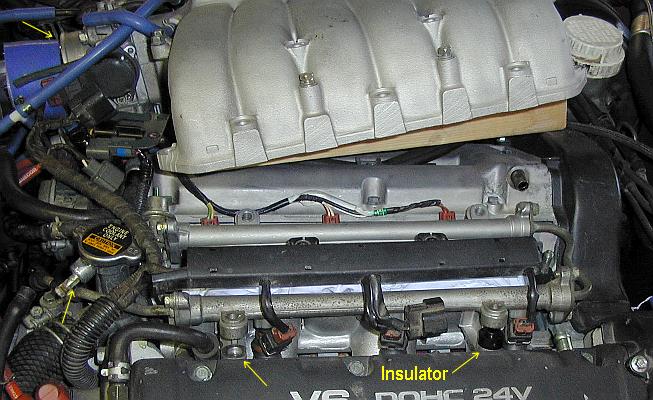
11. Remove the three (12 mm) bolts from the plenum front, the two long (12 mm) bolts from the plenum top, and the two (12 mm) nuts from the plenum front sides. The plenum may pop a little with the release of pressure.
12. Carefully lift the plenum straight up to clear the front studs then tilt toward the passenger side. Prop it up with something. A foot-long 2x4 works perfect. The fuel pressure regulator hose will probably slide off the throttle body, but the rest of the hoses (including the clutch vacuum assist hose on the right side of plenum) should have enough length to move the plenum around without a problem.
13. Cover the intake manifold with a clean rag. You definitely do NOT want anything falling in there. Now is a good time to replace the gasket if it needs it.
Removal
1. Remove the PCV hose from the driver's side of the valve covers.
2. Disconnect the rear EGO sensor electrical connection near the middle of the front rail.
3. Drain a little coolant, just a few ounces, into a clean container. There is a valve and plastic drain hose hear the driver's-side corner of the radiator. Drain 12 ounces if you want add some Red Line WaterWetter when you are done. Now remove the overflow tube from the radiator fluid filler neck.
4. Remove the hoses from the fuel pressure regulator. Remove the vacuum hose and re-attach it to the tube on the throttle body. Slide off the fuel return line hose and set aside.
5. Remove the (10 mm) bolt that clamps down the high-pressure supply line a few inches from the from rail.
6. Disconnect the 3 electrical connectors from the 3-plug bracket that you removed earlier from the passenger-side of the plenum.
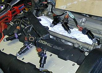
7. Remove the 4 (12 mm) bolts that secure the two fuel rails to the manifold. Be careful to not let any of the 4 insulators fall off. They are grooved to fit into the rail on top and the manifold on the bottom. Just lift the each rail up a little and slide out each insulator. The injectors should come up with the rails and the fuel injector insulators will either be attached to the injector base or remain in the manifold.
8. Gently slide out each injector from the rail with a slight twisting motion. Some fuel may drain out.
9. Retreive any injector insulators that remain in the manifold if you are going to replace them. Forceps work well for this.
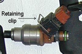
10. Disconnect the injectors from the wiring harness. Pry off each retaining clip. It may help to place your left thumb lightly over the clip while you pry it out with the thin-blade of a pocket knife.
Installation
Before installing the new injectors, I tested each for electrical resistance across the terminals. The standard is 2 to 3 Ohms. Each of mine measured 2.7 Ohms.
1. Connect the new injectors into the wiring harness. The retaining clips worked in the Denso injectors I used. If the clips don't work, they are really not required and can be left off.
2. Place the injector insulators (6) into the manifold recessed areas. You could also slide the insulators onto the injectors, however, I found it easier to be sure of good alignment by putting them into the manifold first.
3. Slide the injectors into the rail with a slight twisting motion. First, apply a very small amount of clean motor oil on the o-ring and top of the grommet. I used a Q-tip. Be sure that no oil gets into the injector.
4. Roughly align the injectors with the holes in the manifold. Don't press down yet.
5. Add the four rail bolts and insulators. Don't drop the insulators into the manifold.
6. Now simultaneously align and insert all six injectors. Take your time and re-check continuously. Keep pressing down till the rails fit tightly to their insulators and the injectors are sitting down fully on their insulators.
7. Tighten the four rail bolts using a torque wrench using 10-13 N-m (7-9 ft-lbs). Don't strip these threads or you are really in for some work.
8. Re-connect the coolant overflow tube.
9. Re-attach the high-pressure fuel supply line bracket.
10. Re-attach the fuel return line hose to the fuel pressure regulator.
11. Put the PCV hose back on and the 3 connectors on the bracket that goes on the passenger's side of the plenum and re-connect the rear EGO sensor.
Post-installation
1. Clean the plenum-to-manifold gasket if it needs it or replace it.
2. Lower the plenum onto the manifold studs. Do NOT attach bolts or nuts at this time. You will need the plenum loose for the next step.
4. Bolt the plenum to the rear two stays first. You may need to apply your weight or tap the plenum with your fist to get the holes to line up. I actually get up on the engine with my knees on the plenum. Be sure to re-attach the grounding cable and oil pipe bracket with the driver-side stay. Insert the two bolts by hand and tighten but do not torque down.
5. With the wire still attached to the EGR pipe gasket, insert the driver-side bolt through the EGR pipe and gasket and into the plenum. Tighten a little by hand. Remove the wire, slide the gasket around, and insert the other bolt. The two EGR bolts can now be tightened (18 N-m).
6. Install the front five plenum bolts and two nuts. Torque the two rear stay bolts, the front five bolts and two nuts to 18 N-m.
7. Now proceed with pre-removal steps 8 to 3 above (in reverse order of course). Be sure to check the fuel pressure regulator hose and the other vacuum hoses.
8. Re-connect the fuel pump electrical connector.
9. Re-connect the battery negative terminal. The disconnected battery reset the ECU.
10. Start the car and let it idle for a few minutes and check for leaks or other problems.
11. Put your stuff back into the rear storage compartment.
Here are the ARC2 settings that worked initially for me (with 15Gs).
LOW: +2% or +1 click
MID: -14% or -7 clicks
HIGH: -6% or -3 clicks
ACCEL: +2% or +1 click (first version with 0 at "6 o'clock")
Page last updated March 17, 2002.