Fuel Pump Relay/Resistor Bypass
in the Mitsubishi 3000GT/Dodge Stealth
by Jeff Lucius
Introduction
It is critically important for turbocharged models that the fuel pump receive the maximum amount of voltage available from the charging and wiring system. The alternator will try to maintain about 13.5 volts into the system. Resistive losses along the current path to the pump will reduce the voltage at the pump to something less than 13.5. If there are less than 12 volts at the pump, the amount of fuel flowing may be much less than expected and perhaps enough less to create lean air-fuel mixtures under heavy boost.
The instructions below show you how to bypass the resistor and relay that the turbocharged 3S models use to reduce voltage to the pump at idle. Please read through the instructions and look at the pictures before attempting this procedure. Before I did this relay/resistor bypass I measured the voltage at the pump using the method shown on my web page 2-fuelpumpvoltage.htm. At idle the pump was receiving about 6.7 to 7.0 volts. I saw from 10.6 to 10.8 volts as boost began to build and then watched that number drop to 10.2 to 10.3 volts as boost hit 15 psi or so and RPM approached redline. After performing the relay/resistor bypass I remeasured the voltage at the fuel pump with the following results.
Cold idle: 11 volts
Warm idle: ~10.6 volts
Warm idle after radiator fan kicked in: 10.35 - 10.55 volts
Acceleration and boost: ~10.5 volts
After taking the measurements above, the voltage at the battery during warm idle was 13.72 volts, which is normal for a properly functioning alternator. The "bypass mod" did not improve voltage to the pump for me. Other owners do report voltage increasing to the 11.5 (acceleration) to 12 (idle) volts range. Perhaps there is increased resistance at some point in the fuel pump electrical circuit in my car, such as at the grounding point.
The tools and supplies needed include 1/8" and 1/4" flat-blade screwdrivers, wire cutter and crimping tool, 12-mm socket and socket wrench with a 3" extension, electrical tape, about 3" of 16 or 18 gauge insulated, multistrand wire, and two crimp-on, male blade connectors. Be sure the ignition is off before performing this work.
Fuel pump electrical circuit
Looking at the circuit diagrams in the service manual, I found the following current path to the pump for turbocharged models.
1) Battery [+ terminal]
2) Fusible link [30A - terminal 4]
3) Ignition switch [IG1]
4) Multipurpose fuse [15A - terminal 12]
5) Engine control relay
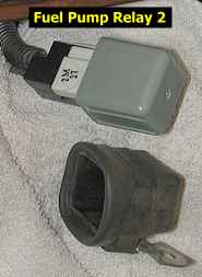
6) Fuel pump relay 2
6a) Resistor [switched by ECU at idle through the pump relay]
7) Fuel pump
8) Chassis ground [-] through fuel pump assembly frame to gas tank to body/frame
Summary
If all you need are pictures then look at these two and go do the modification. The relay is not plugged back into the harness. Be sure to seal the exposed parts of connector with electrical tape. For more detailed instructions please continue reading.
Preparation
1. Battery. With the ignition off, remove the negative battery cable from the battery. Be sure you have security codes for any devices that might need them before you do this.
2. Air cleaner and MAS. Remove the air cleaner and the mass air sensor. This is easy to do with my ARC2 setup. It will be a bit more difficult with a stock setup.
Bypassing the relay and resistor
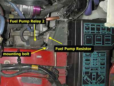
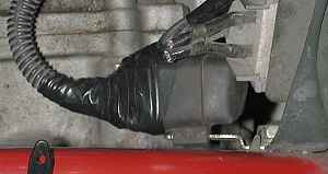
1. Remove the relay. Loosen the 12-mm bolt that attaches the relay to the body untill it can be turned by hand. Remove the bolt by hand and move the relay so it is easier to work on. I placed some shop rags under it to isolate it somewhat and support it (plus it made the pictures easier to take).
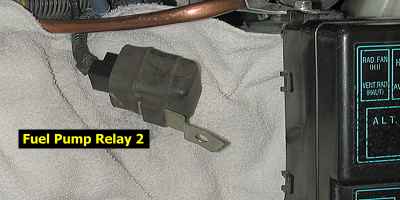
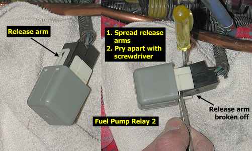
2. Seperate the relay and wiring harness. Roll back the loose edge of the rubber boot and slide the boot off the relay and harness connector. There are two plastic arms that "lock" the harness connector to the relay. The relay is the gray blocky piece and the white plastic pieces are part of it. I broke one of the release arms off by prying it out too far so only use enough pressure to raise the arm enough for the bump on the harness connector to clear. I ended up using a small 1/8" flat-blade screwdriver to hold the remaining arm away from the harness and another screwdriver to pry the harness and relay apart. You will not be putting the relay back on so store it in a safe place in case you want to reverse this modification.
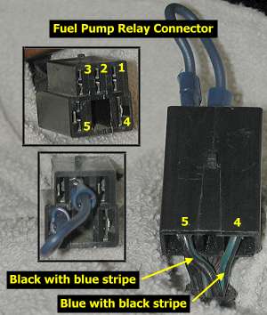
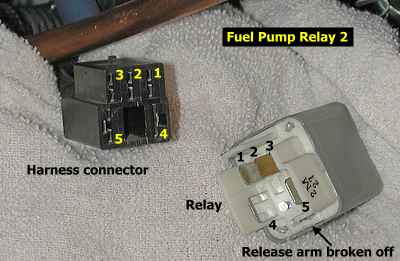
3. Identify the terminals. Look at the partial circuit diagram in the Summary section above. Positive current is supplied to the connector and relay at terminals 3 and 5. Terminal 4 routes power to the resistor and terminal 2 routes power directly to the fuel pump. When the relay is off, power goes through terminal 2, as shown with the yellow highlights. When the ECM grounds terminal one the relay turns on and routes power through terminal 4. We want power to always go from terminal 3 or 5 to terminal 2, thus eliminating the resistor from the circuit. One way to do this would be to cut the wire to terminal 1 so the ECM could never switch the relay on. Another option would be to remove the relay and connector and splice wires to terminals 3 and 2 together. The method presented here is a reversible one. The relay is removed and a short jumper wire connects terminals 5 and 2 together. You could connect terminals 3 and 2 together and achieve the same results. The picture below identifies the terminals for you. If you are ever unsure how the terminals on a connector are numbered, the circuit diagram supplies the color code for the wire. In this case, the wires we want all have a basic black color with a blue stripe. The circuit diagram also shows that the wires are 1.25 mm2 in size (that is cross sectional area). This is equivalant to a 16 gauge wire.
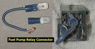
4. Jump the terminals. Cut a piece of 16 or 18 gauge insulated, stranded wire about 2.5 to 3 inches long. Strip the insulation off each end a little and attach male blade connectors. I used crimp-on connectors. Insert the ends of the jumper wire into terminals 2 and 5 of the connector. Use electrical tape to seal the connector up against water, snow, ice, dust, etc. Put pieces over the exposed terminals and then carefully wrap the whole connector. Slide the rubber boot back on and tape it to the wiring harness to reduce chances of dust and moisture from getting to the terminals.
4. Install the connector. Bolt the connector back in. Install the MAS and airfilter. Re-attach the battery negative cable. Start the engine (if you messed this up the fuel pump will not work and the engine will not start) and check your work for shorts or other problems. You should also measure the voltage at the fuel pump to see if it increased. I did not see any significant change, about 10.5 volts before and after this mod. But other owners have scene an improvement.
Page last updated June 15, 2002.