Instructions for Changing the Fuel Pump
in a Mitsubishi 3000GT/Dodge Stealth
by Jeff Lucius
Overview
Changing your fuel pump is one of those tasks that sounds a lot harder than it actually is. In fact, once you have done it, you should feel comfortable about changing it at the side of the road. These instructions are for the novice and you shouldn't need them again after you change your first Stealth/3000GT fuel pump. You will only need a few tools: #2 Phillips screwdriver; flat-blade screwdriver; 14-mm open-end or flare-nut wrench; 19-mm open-end wrench; 8-mm and 7-mm sockets and a ratchet; and a thin-bladed pocketknife. A hand impact tool and hammer could be helpful. There is no need to remove the gas tank. Raising the car will make the task much easier but it is not a necessity. The hardest part may be loosening the fuel-line fittings.
Preliminaries
Having only a 1/4 tank or less of fuel is good, but not required. Raise the car up if you can - ramps, a lift, jack stands. Fold down the rear seat backs and remove the stuff from your rear storage compartment, including the spare tire and both storage bins. I also removed the carpet (2 plastic push-in/pull-out plugs near rear seat) and the cardboard cover (2 Phillips screws in each hinge), to make it easier to work in the compartment. Remove the access cover to the pump assembly on the right side of the compartment floor (4 Phillips screws).
Remove the fuel pump assembly
1. Reduce the fuel-line pressure. Unplug the electrical connection for the pump (to the rear of the blue, two-way valve). It is connector F-16 in the electrical configuration and circuit diagrams. Press down on the top tab and pull it forward. Now try to start the car. It shouldn't.
2. Remove the blue, two-way valve. Slide the valve up off its mounting post on the top of the fuel-pump assembly. Slide the clamp on the back hose off the valve and slide the hose off the valve (twisting can help).
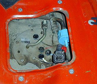
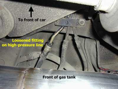
3. Remove the high-pressure, fuel line. This is at the end of the metal pipe coming out of the assembly. It looks like there are two nuts there (or a bolt and a nut). The "bolt" is fixed to the metal pipe and does not turn. The "nut" is attached to the rubber hose. Attach a 14-mm flare-nut wrench (an open-end wrench will do) to the fixed bolt on the metal pipe. Use a 19-mm open-end wrench to loosen the nut on the hose by pushing (or pulling) the wrench toward the outside (passenger-side) of the car. Make sure that the "bolt" and metal pipe do not move or bend. I found it easier to work inside the compartment with a foot on the 14-mm flare-nut wrench. Once the nut is loose, you may be able to remove it completely by twisting the rubber hose many times. However, it will be easier to loosen the fitting at the other end of that hose in front of and above the gas tank. Here is where it is helpful if the car is raised. Both pieces spin on the fitting at the front of the hose. Loosen the fitting using the 19-mm wrench on the hose "nut" and the 14-mm wrench on the metal pipe "bolt". The bolt rotates counterclockwise and the nut clockwise, as you are laying on your back, head towards front of car, looking up at the fitting. It is not necessary to disconnect this fitting; just loosen it. Be sure to wear glasses or safety goggles when working underneath the car.
NOTE:The last time I removed my fuel pump I found it easier to leave the high-pressure line attached to the pump assembly and to remove the forward end of the hose (near the front of the fuel tank). Then the hose is removed with the assembly. The assembly must be maneuvered a bit more than in the procedure described above.
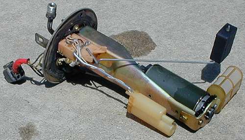
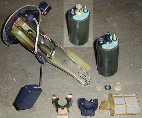
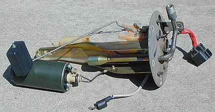
4. Remove the fuel-pump assembly. Remove the six 8-mm nuts on the top of the assembly. The pump assembly is now ready to lift out. Note the three, rubbery protrusions along the edge of the assembly top. These are part of a rubber gasket that goes between the assembly top and the compartment floor. Use your fingers to be sure that this gasket does not tear as you remove the assembly. You will have to rotate and tilt the assembly to get it out of the tank.
Remove and replace the pump
1. Drain the fuel out of the assembly. Let the fuel drain out of the top and bottom of the assembly (in an environmentally conscious manner, of course). Does the new pump look like it matches? Clean any junk off the filter; don't damage the screen. Take care not to bend the wires attaching the float and low-level sensor while handling the assembly.
2. Remove the filter. Remove the screw from the bottom bracket. I had to use a hand impact tool (Sears PN 47763 or 47762, $20) to loosen it without stripping the head. Remove that bracket and the rubber grommet. Using a thin-blade pocketknife (or similar tool), gently pry off the washer that holds on the filter. Remove the filter.
3. Remove the pump. Pull the pump straight down. Only a rubber O-ring holds it in. There are no interlocking pieces. Remove the 7-mm nut and the wire from the positive terminal. Remove the nut and the wire from the negative terminal.
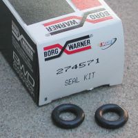
4. Transfer parts to your replacement pump. With your finger on top of the white plastic piece on top of the pump, gently pry up with a flat-head screwdriver (or similar tool) in small increments around the piece so that it moves up in a "parallel" manner until it comes off. Take off the O-ring and the other white plastic piece. Note that one or more of these three pieces may have remained in the pickup tube; if so, then carefully remove them. By hand only, put these pieces on your new pump. The top piece just snaps on. Please note that the o-ring that seals the pump into the fuel pickup tube can be damaged during installation and cause starting and driveability problems. Mitsubishi does not sell this o-ring but the following one is a replacement: Borg-Warner fuel injection seal part # 274571 ($1.99 at Pep Boys, $3.99 list price), which has NAPA cross referenced part #2-12093 seal kit.
 5. Install the new pump. Reattach the negative wire. Slide the pump into the pickup tube. Attach the positive wire. Put the (cleaned) filter on and its "washer". Put the rubber piece back on the base and the base plate. I used the hand impact tool to tighten the screw.
Stock wiring assignments at the pump assembly electrical connector:
Black w/ red stripe: Ground
Black: Ground on pump assembly frame
Black w/ blue stripe: Power
Yellow: Fuel gauge
Yellow w/ blue stripe: Low fuel warning
Re-install the pump assembly
1. Install the assembly. Look over the assembly to make sure all screws and nuts are tight and the filter and top gasket (the one with the three protrusions) are clean. Carefully clean off the top of the tank around the opening. Is the inside of the gas tank in good shape? Slide the assembly into the tank. Tighten the six 8-mm nuts down evenly, in a pattern like you would your wheel lug nuts. I couldn't find any torque specifications, just don't tighten too much.
2. Re-attach the high-pressure fuel line at the pump. Remember the assembly-side "bolt" does not spin and do not bend the metal tube. Now go tighten the other end of the hose (in front of the tank) if you loosened it before. Tightening torque is 25 ft-lb (35 Nm) near the pump end and 22 ft-lb (30 Nm) at the other end, if you can figure out how to use a torque wrench on these parts.
3. Re-attach the valve and electrical connector. Re-attach the blue two-way valve to its post and and attach its hose and clamp. Plug the electrical connector back together.
4. Start the car and look for leaks. If everything is OK put the access cover back on and your rear compartment stuff back together and go brag about changing your own fuel pump. See it wasn't that hard was it?
Fuel pump electrical circuit
Looking at the circuit diagrams in the service manual, I found the following current path to the pump for turbocharged models.
1) Battery [+ terminal]
2) Fusible link [30A - terminal 4]
3) Ignition switch [IG1]
4) Multipurpose fuse [15A - terminal 12]
5) Engine control relay
6) Fuel pump relay
6a) Resistor [switched by ECU at idle through the pump relay]
7) Fuel pump
8) Chassis ground [-] through fuel pump assembly frame to gas tank to body/frame
Page last updated June 15, 2002.