CONNECTORS
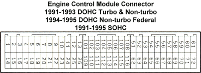
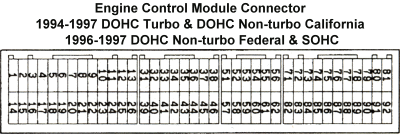
These diagrams show the connector configurations and terminal numbers for the three different types of ECU connectors. Imagine you are looking right at the connector on the ECU when viewing these diagrams. Note that 1994-1995 Federal DOHC non-turbo models retain the 3-piece connector.


| Summary of ECM Connector Styles | |||||||||
|---|---|---|---|---|---|---|---|---|---|
| A=3-pc, 2-row; B=4-pc, 2-row; C=3-pc, 3-row | |||||||||
| Model | '91 | '92 | '93 | '94 | '95 | '96 | '97 | '98 | '99 |
| SOHC | A | A | A | A | A | B | B | C | C |
| DOHC NT CAL | A | A | A | B | B | B | B | C | C |
| DOHC NT FED | A | A | A | A | A | B | B | C | C |
| DOHC Turbo | A | A | A | B | B | B | B | C | C |
TERMINAL ASSIGNMENTS
SOHC: 1991 to 1993
DOHC Non-turbo and Turbo: 1991 to 1993
3-piece connectors; Figures from 1992 Dodge Stealth Service Manual
Page 1 (52 KB)
Page 2 (52 KB)
Page 3 (52 KB)
Page 4 (61 KB)
Page 5 (51 KB)
Complete listing of ECU terminals and assignments for 1991-1993 DOHC engines:
misc/3s_1991-1993_ecu_pins.xls
SOHC Federal: 1994 to 1995
DOHC Non-turbo Federal: 1994 to 1995
3-piece connectors; Figures from 1994 Dodge Stealth Service Manual
Page 1 ( KB)
Page 2 ( KB)
Page 3 ( KB)
Page 4 ( KB)
Page 5 ( KB)
SOHC: 1996 to 1997
4-piece connectors; Figures from 1996 Dodge Stealth Service Manual
Page 1 (60 KB)
Page 2 (55 KB)
Page 3 (51 KB)
Page 4 (53 KB)
Page 5 (19 KB)
DOHC Non-turbo California: 1994 to 1997
DOHC Non-turbo Federal: 1996 to 1997
DOHC Turbo: 1994 to 1997
4-piece connectors; Figures from 1992-1996 Mitsubishi 3000GT Service Manual
Page 1 (28 KB)
Page 2 (22 KB)
Page 3 (24 KB)
Page 4 (22 KB)
Page 5 (25 KB)
Page 6 (24 KB)
SOHC: 1998 to 1999
Figures from 1999 Mitsubishi 3000GT Service Manual
Page 1 (30 KB)
Page 2 (27 KB)
Page 3 (29 KB)
Page 4 (21 KB)
DOHC Non-turbo and Turbo: 1998 to 1999
Figures from 1999 Mitsubishi 3000GT Service Manual
Page 1 (32 KB)
Page 2 (27 KB)
Page 3 (27 KB)
Page 4 (27 KB)
Page 5 (26 KB)
| Some ECM Terminals for DOHC Turbo Models | ||||
|---|---|---|---|---|
| Function | 1991-1993 | 1994-1995 | 1996-1997 | 1998-1999 |
| Injector #1 (for IDC) | 1 | 1 | 1 | 1 |
| Eng. ign. signal (RPM) | 101 | 58 | 51 | 45 |
| Throttle pos. sensor | 64 | 84 | 84 | 78 |
| Idle position switch | 67 | 87 | 87 | 79 |
| Speed | 66 | 86 | 86 | 80 |
| Front O2 sensor | 55 | 75 | 75 | 72 |
| Rear O2 sensor | 56 | 76 | 76 | 71 |
| IG power (+12V switched) | 62 | 82 | 82 | 99 |
| Ground for ECM | 13 or 26 | 13 or 26 | 13 or 26 | 46 or 58 |
| Ground for TPS, others | 72 | 92 | 92 | 49 |