| Products Used for Battery Move To Rear Compartment |
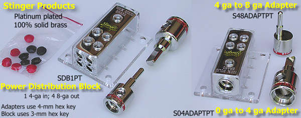
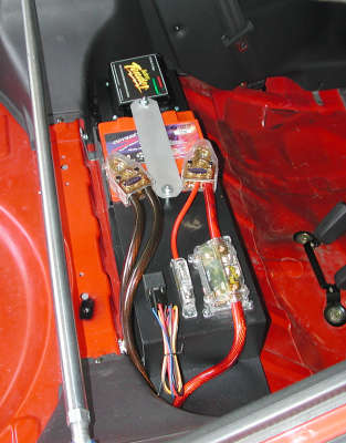
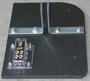
| Stinger power distribution block |
SDB1PT |
$16 |
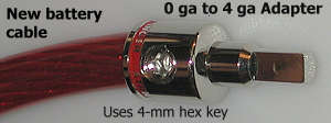
| Stinger 0 ga to 4 ga adapter |
S04ADAPTPT |
$8 |
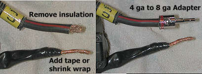
| Stinger 4 ga to 8 ga adapter |
S48ADAPTPT |
$8 |
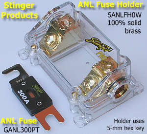
| Stinger ANL (wafer) fuse holder |
SANLFH0W |
$34 |
| Stinger 300A ANL fuse |
GANL300PT |
$12 |
| Stinger 0 ga ring connectors (2) |
S0PRG |
$4 |
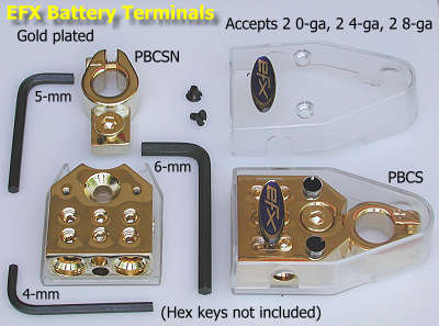
| EFX battery terminals |
PBCSN, PBCS |
$52 |
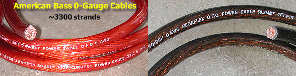
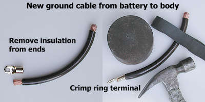
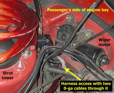
| American Bass 0-ga, ~3300-strand, insulated cables (13' each) |
- |
$77 |
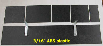
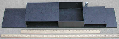
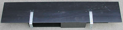
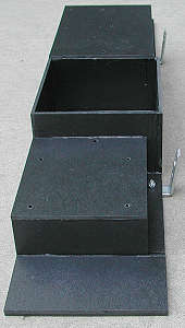
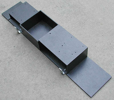
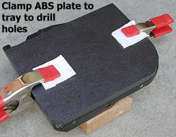
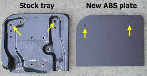
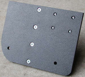
| 3/16"-thick ABS sheets, black, textured one side |
- |
~$30 |
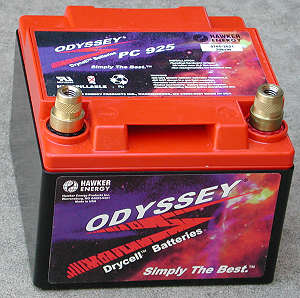
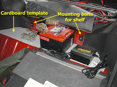
| Odyssey PC925MJT battery |
- |
$106 |
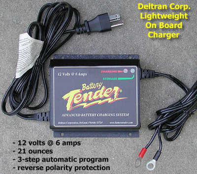
| Deltran lightweight on-board battery charger |
- |
$90 |