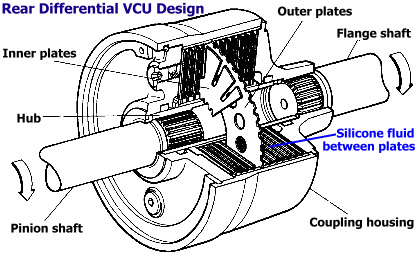
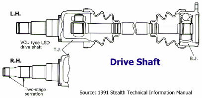
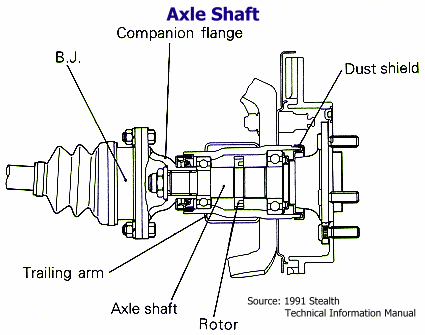
Illustrated Guide to the Mitsubishi 3000GT AWD System

by Jeff Lucius

These pages are still in development. I will add more pictures as I am able to disassemble components or as others send them (pictures or components) to me. If you have comments about this web page or corrections for its contents, please send an email to jlucius@stealth316.com.

Part 1  Acknowledgments
Overview
Part 2  Transaxle Assembly
Transaxle Problems
Part 3  Center Differential/Viscous Coupling Unit
Part 4  Synchronizers
Part 5  Rear Differential, Driveshaft, and Axle Assemblies
Part 6  Propeller Shaft Assembly
Front Driveshaft and Axle Assemblies
Gear Reduction Ratios
Speed in Gears


Rear Differential, Driveshaft, and Axle Assemblies

The differential carrier and the axle housing are connected by a driveshaft. The right-side driveshaft is longer than the left-side driveshaft. A tripod joint (TJ)-style CV (constant velocity) joint connects the driveshaft to the differential and a Birfield joint (BJ)-style CV joint connects the driveshaft to the axle housing near the wheel. The TJ-BJ combination maintains rotational velocity completely even when flexed. It can withstand heavy loads and shock, and offers a high power-transmission efficiency, low vibration, and low noise.

The TJ is used on the differential side of the driveshaft because it slides easily in the axial direction to absorb the change in distance between axle and differential caused by suspension motion. The BJ is used on the wheel side of the shaft because of its compact size and its ability to operate over large deflection angles.

The differential uses lower-friction torque bearings and oil seals to improves power performance and fuel consumption. The differential is the standard pinion and side gear design. Incorporated into the left-side side gear is the limited-slip differential (LSD) case which uses a viscous coupling unit (VCU) to reduce slipping of the rear wheels. The 4-wheel steering oil pump is mounted on the top of the differential and recieves power from a drive gear inside. There are cooling fins on the differential carrier. The differential carrier is elastically mounted on the suspension cross member using supports with bushings.

The axle shaft is a semi-floating type supported by ball bearings in the housing. There is a speed-sensing rotor on the axle shaft on ABS equipped models. The dust shield prevents mud and dirt from being deposited around the outer bearing.

Rear Differential and Axle Assemblies 2

Rear Differential and Axle Assemblies 1

Rear Differential Disassembly

Limited Slip Differential

Rear differential VCU design

Drive shaft

Axle shaft

Back to top of this page
Part 4   Part 4          Part 6    Part 6

Back Home Forward
Except for the small gif and jpg images, the content, images, photographs, text, and multimedia displayed are Copyright ©2000-2002 by Jeff Lucius and K2 Software. All rights reserved. No part, section, image, photo, article, or whole of this site may be reposted or redisplayed without permission of the author.
Page last updated March 17, 2002.