Illustrated Guide to the Mitsubishi 3000GT AWD System
by Jeff Lucius
These pages are still in development. I will add more pictures as I am able to disassemble components or as others send them (pictures or components) to me. If you have comments about this web page or corrections for its contents, please send an email to jlucius@stealth316.com.
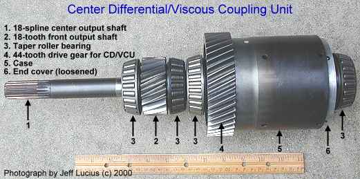
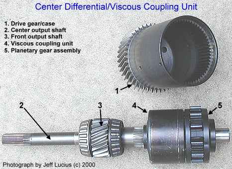
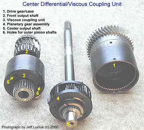
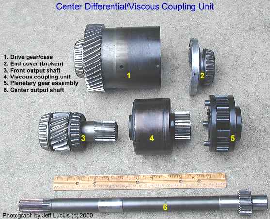
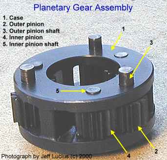
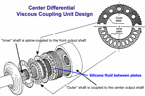
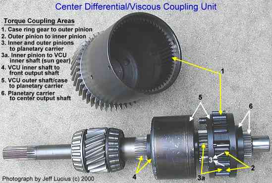
The CD/VCU is the heart of our AWD system. While it is possible to further disassemble the CD/VCU than what the pictures below show, these are the parts that are easily disconnected. Together, the parts weigh about 25 lbs (about 11.5 kg).
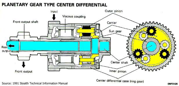
The steel case has a helical drive gear (44 teeth) incorporated on the exterior at one end and a ring gear (60 teeth) on the interior surface at the other end. Torque from the transaxle intermediate shaft (a helical gear, 32 teeth for the W5MG1, 36 teeth for the W6MG1) is transmitted through the drive and ring gears on the case to a planetary gear assembly. The pinion "planet" gears are coupled to the inner shaft of the VCU which in turn is spline-coupled to the front output shaft. The outer VCU shaft and case are directly connected to the planetary carrier which is spline-coupled to the center output shaft. The front output shaft transmits torque to the front differential. The center output shaft transmits torque directly to the transfer case and from there to the rear differential.
Inside the VCU, plates are alternately attached to the inner and outer shafts and rotate in a silicone fluid. When there's a difference in rotational speed between the two shafts, the plates try to shear the fluid, causing the fluid to heat and expand and "lock" the plates together. This causes a torque transfer from the wheels that are slipping (connected to the faster-rotating shaft and plates) to those that are rotating slower (with the better traction).
Operation
The topic of "torque split" inside the CD/VCU is one that is often misunderstood. Before explaining how the engine torque is split between front and rear axles (or more directly, front output shaft and center output shaft, respectively), I need to quickly review gear ratio fundamentals.
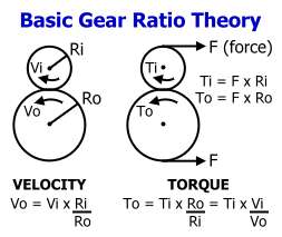
The figure to the right shows the basic relationships common to all gear types. Gears work by transmitting force (or loads) at the teeth of the gear. The circles represent the pitch diameters of two gears. The pitch diameter is slightly smaller than the diameter of the gear itself and is used to determine the gear ratio (or torque ratio) and speed ratio (or angular velocity ratio). For spur, helical, and bevel gear sets (as well as some other types), the number of teeth on each gear can be used instead of the pitch diameter to calculate gear ratios. The smaller of the two gears is called the pinion; the larger gear is called the drive gear. A drive gear that has twice the pitch diameter of the pinion gear will also have twice the number of teeth. Several gears connected together are called a gear train. In general, the overall gear ratio of a gear train is the product of the individual gear ratios.
If there is only one force acting to turn a gear, then torque (or a force that tends to rotate an object) is equal to the force component that is tangential to the pitch circle times the radius of the pitch circle. From the figure, we can see that torque, To, will be larger at the larger gear, but the angular velocity, Vo, will be smaller. The relationship that must be preserved is To x Vo = Ti x Vi. So if torque increases then velocity decreases to conserve angular momentum (the rotational analog of Newton's Third Law, one of the most fundamental relations of mechanics).
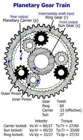
A planetary gear train is an assemblage of three components: a ring gear, a planetary carrier with one or more pinion gears ("planets"), and a central sun gear. The ring gear, pinion gears, and sun gear in our CD/VCU are spur gears, which have straight teeth that are parallel to the shaft. These same gears in the planetary gear train used in the automatic transaxle in the FWD version of our cars are helical gears, which have curved teeth that are at an angle to the shaft. The ring, carrier, and sun all rotate on the same fixed axis. The pinion gears rotate on axes that move with the carrier. When there are multiple pinions, torque from the ring gear is distributed evenly between them.
To determine the gear ratios in a planetary gear train, one of the three components is held stationary (also called locked). In an automatic transaxle, the different gear ratios are achieved by locking the different components of the planetary gear. Often when a planetary gear is used in a center differential (such as in the new Mitsubishi Montero automatic-transaxle 4WD), the carrier is the driving component and both the ring and sun turn at different speeds to split torque unevenly (such as 33/67 front/rear for the Montero) between ring and sun gear (no component is actually locked).
In the case of our center differential, the ring gear is the driving component, receiving torque from the transaxle intermediate shaft through the CD case. To determine the amount of torque applied to the sun gear, the carrier is assumed locked and normal gear ratio multiplication is used. The 60-tooth ring gear turns the 13-tooth outer pinions (13/60 gear ratio). The outer pinions and inner pinions have the same number of teeth so there is no change in torque (gear ratio = 1). The inner pinions turn the 27-tooth sun gear. The overall gear ratio is 13/60 times 27/13 or just 27/60 equal to 0.45. So when the carrier is locked (that is the rear axles are not turning) the sun gear will have a torque value only 45% (27/60) of the torque at the ring gear. Of course the velocity of the sun gear is 60/27 (or 2.2222) times that of the ring gear. The sun gear and ring gear rotate in the same direction.
When the sun gear is locked, the angular velocity and torque of the carrier are only slightly more complicated to determine. Using the figure below that shows the relative motion of the different gears, imagine that the sun is stationary and the ring gear is rotating clockwise. In one revolution of the ring gear, its 60 teeth cause the outer and inner pinions to rotate 60/13 times (gear ratio = 13/60). The inner pinions must "walk" along on the 27 sun-gear teeth (gear ratio = 27/13). However, when the ring gear rotates one tooth it also "pushes" the carrier one tooth on the sun gear. So the carrier actually only rotates 60 - 27 teeth relative to the ring gear in one revolution giving it an "effective" 33 teeth. The gear ratio is then 33/60, so the torque that would be transmitted to the carrier and eventually the rear axles when the sun gear is locked (that is the front axles are not turning) is 55% of the torque at the ring gear. The velocity of the carrier would be 60/33 (or 1.8181) times that of the ring gear. Though the relative motions are opposite, the "push" effect causes the carrier to rotate in the same direction as the ring gear.
For completeness, consider the ring gear locked, such as when the engine is off and the clutch is engaged, and the carrier as the driving gear. The sun gear will turn in the opposite direction with a gear ratio of 27/33. The sun gear (front output shaft) would rotate 33/27 (or 1.2222) times as fast as the carrier (center output shaft).
To verify that these motions are indeed what happen, I used tape to mark the CD/VCU case, the front output gear, and the center shaft to measure the rotation amounts. Holding the center shaft motionless (carrier locked) one turn of the case (ring gear) resulted in about 2.3 turns of the front output shaft (sun gear) in the same direction. Holding the front output shaft motionless (sun locked) resulted in about 1.9 turns of the center shaft for one turn of the case, in the same direction. The front output shaft turned about 1.25 times as fast in the opposite direction as the center output shaft when I held the case locked.
So what happens when the ring, carrier, and sun are all free to rotate with respect to each other? The conservation of angular momentum rule still applies and the torque split between front and center output shafts is inversely related to their relative rotation rates with respect to the ring gear. Two equilibrium situations can occur.
The first equilibrium situation is that the two output shafts are free to rotate independently (without differential limiting by the VCU). This situation could occur if all four tires are not contacting the same surface, or either the transfer case or front differential are not connected to the corresponding CD/VCU output shaft. The carrier will rotate 60/33 (1.8181) times as fast as the ring gear. The sun gear will rotate 33/27 (1.2222) times as fast as the carrier or 60/27 (2.2222) times as fast as the ring gear. Torque distribution would be 45% to the sun gear and 55% to the carrier. To preserve angular momentum (TrVr = TcVc + TsVs), the actual torque assignments would be 0.225 to the sun gear and 0.275 to the carrier if the input torque was one unit, because the input torque must be split between two output gears.
The other equilibrium situation would be that all gears rotate at the same rate so that the center differential acts as a direct drive. This situation occurs for our cars whenever all cases and shafts are connected and all tires rest on the same surface with the same traction level (for example, all tires are on dry pavement or all are on ice). As soon as the wheels begin to turn, the center and front output shafts turn in the same direction at nearly the same velocity (the transfer case times rear differential gear ratios equals the front differential gear ratio). The VCU helps to enforce this. When the output shafts rotate at the same velocity, torque is split evenly (50/50) between them. To preserve angular momentum, the actual torque assignments would be 0.50 to the sun gear and 0.50 to the carrier if the input torque was one unit.
A non-equilibrium situation occurs when one set of axles has less traction than the other set. The torque-split would be determined as described in the scenarios above when either the sun gear or carrier is locked, or by the relative rotation rates of the carrier or sun gear with respect to the ring gear. The planetary-gear center differential would act similar to the typical pinion-and-side-gear open differential, where one axle set spins faster than the other. However, in our center differential, the VCU provides the differential limiting that forces the carrier and sun gear to rotate at close to the same rate, distributing torque evenly.
Mitsubishi promotional and technical literature either implies or states that torque is split 45/55 front/rear when the car is being driven down the road. This is clearly not true under normal driving conditions and here are the reasons why.
First, if in fact output torque is not split equally between the two output shafts, then the output-shaft angular velocities are not equal (from the principle of conservation of angular momentum). As shown above, when the relative rotation rates of two gears are not equal then the gear ratio is not equal to one. Mitsubishi correctly does not claim any gear ratios associated with the CD/VCU other than the primary (intermediate shaft to CD case), front differential (CD output shaft to front differential), and transfer case (CD output shaft and the bevel gears inside transfer case). This means that in non-slip situations, CD output velocities are the same as input velocities and CD output torques are equal, though each is half of input torque.
Second, the overall gear ratio is identical for both front and rear axles after the primary gear ratio (for the 5-speed, 22/27 x 39/11 = 52/18). This means that the two CD output shafts rotate at the same velocity when the car is moving straight down the road with good traction all around, and so torque is split evenly front and rear. Now if one axle set begins to slip and the VCU has not limited the difference in rotation rates, then torque can be unevenly distributed. For the claimed 45/55 distribution, the front output shaft (sun gear) would have to turn 1.1111 times as fast as the ring gear and the center output shaft (carrier) would turn 0.9090 times as fast as the ring gear [1 = (0.45 x 1.111) + (0.55 x 0.9090), where Tr=1 unit and Vr=1 unit].
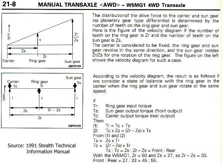
Third, the seemingly technical explanation of torque split given in the 1991 Stealth Technical Information Manual (shown in the figure below) fails on internal consistency checks. The upper "velocity diagram" is correct and was described above in the "carrier locked" scenario. The lower velocity diagram is correct in appearance but is interpreted incorrectly. In Mitsubishi's interpretation of the lower velocity diagram two premises are stated. The first one is an incomplete statement of the input and output torque relationship. The complete expression is
(Tr x Vr) = (Tc x Vc) + (Ts x Vs).
The expression "Tr = Tc + Ts" is only true when all velocities are equal and Tc = Ts (a 50/50 torque split). But let us assume for the sake of argument that Tc and Ts are not equal and check the rest of the expressions for consistency. The second premise, "Tc x Zs = (Zr - Zs) x Ts", where Z represents the number of teeth on a gear, is rearranged with substitution (set Zc = Zr - Zs) to form the following expressions.
Tc = (Zr - Zs)/Zs x Ts
Tc = Ts x (Zc/Zs) (analogous to To = Ti x (Ro/Ri) shown above), or
Ts = Tc x (Zs/Zc).
Mitsubishi then argues that Ts = Zs x Tr and Tc = Zc x Tr (the problem with these two expressions is that Zr is missing!). From the second premise that Ts = Tc x (Zs/Zc), we can perform substitutions and rearrangements to get the following expressions.
Ts = Zs x Tr = Tc x (Zs/Zc), or
Tc = Ts x (Zc/Zs), and
Tr = (Tc/Zs) x (Zs/Zc) = Tc/Zc.
Now using Tr = Tc + Ts and Tc = Ts x Zc/Zs, and simplifying we get the following.
Ts = Zs x Tr = Zs x (Tc + Ts) = (Zs x Tc) + (Zs x Ts)
Ts = (Zs x [Ts x Zc/Zs]) + (Zs x Ts)
Ts = (Zc x Ts) + (Zs x Ts)
Ts = Ts x (Zc + Zs).
This last expression is true only if Zc + Zs = 1, which is clearly false. Zc equals 33 and Zs equals 27. Mitsubishi's analysis fails on internal consistency. In addition, the first premise (Tr = Tc + Ts) is true only if Mitsubishi's conclusion (that Tc is not equal to Ts) is false.
In summary, the claimed 45/55 front rear torque split for the AWD 3000GT/Stealth only applies when the VCU is not limiting differential rotation rates and 1) the transfer case is removed so that center output shaft can rotate at a different rate than the front output shaft, 2) the front wheels are slipping and so rotate slightly faster than the rear axles, or 3) the car is just beginning to move (analogous to either the carrier or sun gear being locked). Once the car is moving and there is the same traction at all wheels, torque is split evenly (50/50) between transfer case and front differential.